Wellsaw 613 User Manual
Page 7
2. Open Idle and Drive Wheel guards.
3. Loosen Rite Tension take-up screw and remove old
blade. In the event of a broken blade, be sure Rite
Tension is open by turning take-up screw counter-
clockwise at least six [6] turns.
4. Uncoil new blade. Make certain the blade teeth
point in the direction of blade travel which is toward
the motor. If not, turn blade inside out to have the
proper tooth direction.
5. Place new blade on the guides and the band wheels.
6. Grasp blade on frame side and push it toward guide
bracket beam to hold it in position while turning the
Rite Tension take-up screw.
7. Tighten blade to proper tension. Blade is properly
tensioned when the take-up screw is tightened until the
mechanism bottoms out.
Maintenance Instructions
Blade Guide Alignment
To properly align the saw blade for a straight and
accurate cut, do the following.
1. Check the stationary vise jaw. Make sure it is
square. To do this, place a combination square against
the vise jaw slot in the saw bed. Slide the square
toward the stationary vise jaw. Make the necessary
2.
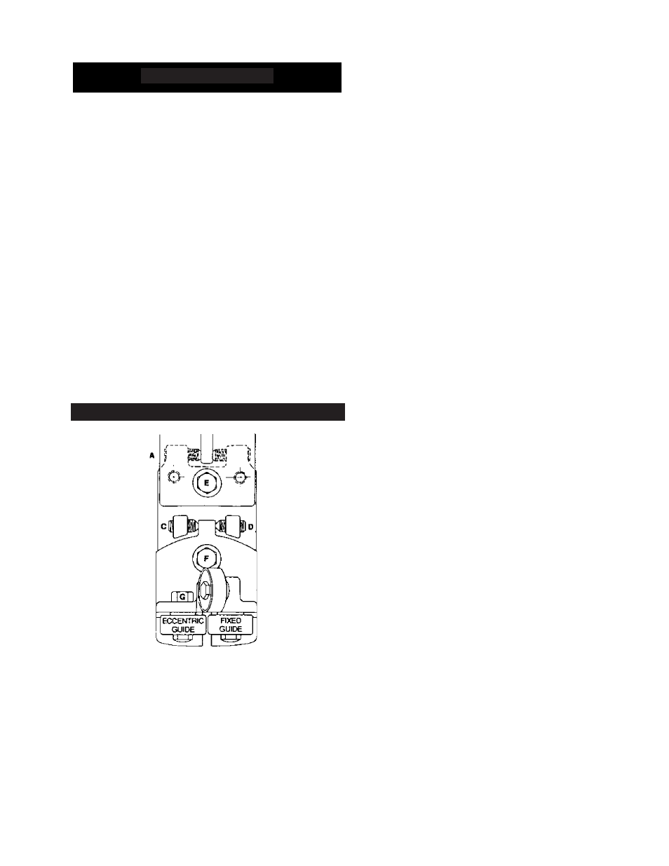
This adjustment is. made with the top two Allen
screws on the roller adjusting block of the guide arm.
Looking at the drawing, you will see these adjusting
screws labeled "A" and "B".
3.
To make a vertical adjustment of the saw blade, so
that the cut is square from top to bottom, the blade
must be set so that it is perpendicular to the bed. In
making this adjustment, clean the saw bed first.
4.
Set the rule of the combination square on the saw
bed with the end of the rule butted against the blade
above the set of the saw teeth. Use a 1-1/2 thousandths
(.0015") shim and slide it along the top and the bottom
edge of the rule where it meets the saw blade. If the
shim slides between the blade and the rule at either the
top or bottom, the roller supports must be adjusted by
using the bottom Allen screws marked "C" and "D" to
obtain the correct 90° angle.
Adjust the side roller guides with the eccentric axle
until both rollers contact blade. When this adjustment
has been made, the roller should be adjusted so that
the PATH OF THE BLADE IS STRAIGHT and the
blade is not forced to curve around the rollers. The top
roller guide should be in contact with the top of the
blade at all times. When running idle, this contact
pressure should be very light
Wheel Pitch Adjustment
If the saw blade runs too low or off the wheels, or runs
too high and rubs the wheel flange, a wheel pitch
adjustment must be made. Loosen the blade before
making the following adjustments.
Idler Wheel
Blade running too low or off the wheel. Adjust the Idler
Wheel Block. Loosen one-half [112] turn the two cap
screws in the block closest to the take-up screw end.
Tighten by one-half turn [112] the two cap screws in the
opposite end of the block. Repeat if more adjustment is
necessary.
Blade running too high and running against the Idler
Wheel Flange. The blade can become distorted, its top
edge rolled over and the wheel flange will wear exces-
sively. To correct this, loosen by one-half [112] turn the
two cap screws opposite the take-up screw on the wheel
block. Tighten the two cap screws closest to the
7
Placing Blade on Saw
1. Raise saw frame.
adjustment. If you then find the saw blade is not
square with the stationary vise jaw, the blade must be
adjusted.