58b service parts changes – Wellsaw 58BW User Manual
Page 16
16
ELECTRICALS
Before 17240 to 21035
100670-1 (Switch Only) or 102888 Switch Box Assembly
Beginning 20855
105869
Safe Start Plus and Cord Set
Beginning 21036
120228
Switch Assembly & 100846-16 Motor
BLADE GUIDES
To Serial Number 11751
102858
Frame Ratchet
102908
Guide Bracket Idle End
102912
Guide Bracket Drive End
101322
Roller
Guide
Assembly
From Serial Number 11752
105828
Frame Ratchet
105832
Idle Guide Bracket End
105830
Guide Bracket Drive End
101322
Roller Guide Assembly
BLADE GUARDS
To Serial Number 11885
102963
Blade Guard Idle End
102949
Blade Guard Drive End
102961
Pivot Rod
Current Idle Wheel Guard Assembly could replace old assembly
using the following parts:
105868
Idle Wheel Guard Assembly
105860
Roller
Axle
WHEEL KITS
To Serial Number 22020
102931
Wheel and Handle Kit for fi eld installation
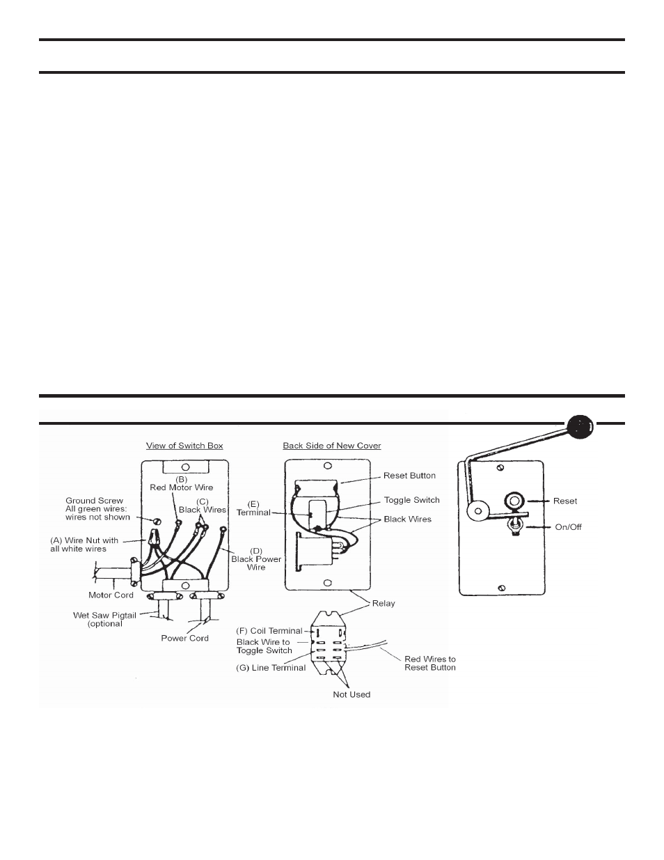
1. Disconnect
power.
2.
Remove existing cover.
3.
Remove wire nut (A) and add white pigtail with push connector.
4.
Cut off red motor wire (B) from both ends of motor cord.
5.
Connect black wire (C) from motor and wet saw pigtail (C) to toggle switch terminal (E).
6.
Cut off existing terminal on black power wire (D) and replace with push terminal supplied.
7.
Connect new white pigtail to relay coil terminal (F).
8.
Connect black power wire (D) with new push terminal to relay line terminal (G)
9.
Install cover on switch box.
10. Saw operation. Push reset button only after loss of power. Normal saw operation is by toggle switch.
122029 Switch Box Assembly
58B Service Parts Changes