The basics of magnetic attraction, Uidelines for the, Eduction of – Walker Magnetics TURBOMILL 40B User Manual
Page 14: Ated, Olding, Apacity, Asics of, Agnetic, Ttraction, Igure
O.S. WALKER Co. Inc., Turbomill Electroperm Chucks
DD15508M.doc Rev. ~, September 17, 2002
4-3
4.4 Guidelines for the Reduction of Rated Holding Capacity
Each Walker chuck model is rated for different holding limits. Load characteristics will affect
the holding capacity of the chuck. The holding guidelines for the chuck models are shown
below.
THIS TABLE PROVIDES SOME REDUCTION FACTORS FOR MATERIAL OTHER THAN
SAE 1020 STEEL.
Table 4-1
Reduction Factor for material other than SAE 1020 Steel
Reduction factors for material other than SAE 1020 Steel
Materials
Reduction Factor
Cast Steel
0.90
3% Silicon Steel
0.80
SAE 1095 Steel
0.70
416 Stainless Steel
0.50
Cast Iron (non-chilled)
0.45
Pure Nickel
0.10
For other materials, contact O.S. Walker
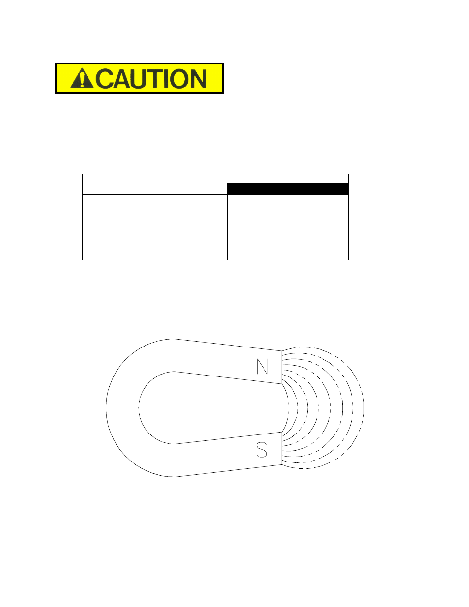
4.5 The Basics of Magnetic Attraction
Magnetic lines of force (flux) exist between the north and south poles of a magnet.
Figure 4-1 Basic Magnetics
This flux can be used to attract and hold ferrous components, which when placed in a flux
field have poles induced in them of opposite polarity to the magnet. These are attracted to
the magnet until contact occurs. As the ferrous parts get closer to the magnet, more flux lines
are induced into the work, as the distance decrease and flux lines increase, the holding force
increases until contact is made and the maximum force is achieved.