Enjoy your mount – Video Mount Products LCD-2537B User Manual
Page 4
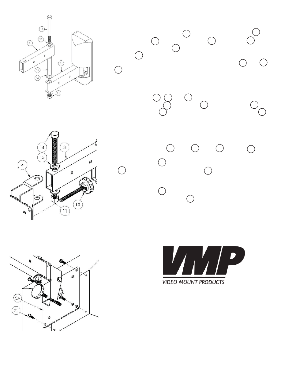
Step 5
If your application calls for the double arm confi guration, at-
tach the front force arm to the rear force arm using
the metal pin , the long spacer , washers on the
top and bottom and between the two arms), and the ny-
lon nut . If your application calls for the single arm or near
fl ush mount confi guration insert the short spacer into or
and continue to the next step.
Step 6
Attach the swivel bracket assembly from step 2 to the appropri-
ate force arm , , or depending on your application
using a 3/8” screw , washers , and nylon nut . Insert
adjustable screw into the back of the swivel bracket for
use when tilting the monitor.
Step 7
Attach the mounting plate assembly from step 2 to your fl at
panel using the M4
(#21)
, M5
(#22)
, M6
(#23)
or M8
(#26)
screws
as appropriate. NOTE: If you are using M4 screws with the Large
Mounting Plate
(#5B)
then you have to use the small washers
(#27)
provided with the M4 screws
(#21)
.
Step 8
Insert end plugs into the force arms. For cable manage-
ment, insert the cable clips by pushing the arrow ends into
the square holes in the force arms.
Please verify that all nuts and screws are securely tightened.
Step 5: Attaching the front
force arm to the rear force arm
Step 6: Attaching the pivot
bracket to the front force arm
Step 7: Attaching the fl at panel
to the mounting plate (M4
Screws (#21) shown)
WARNING: The installer of these products must verify that
the mounting surface, ceiling or wall, will safely support the
combined weight of all attached equipment and hardware.
Video Mount Products will not be held liable for the improper
use or installation of its products.
Enjoy Your Mount!
20
19
10
2
11
16
11
9
8
15
7
3
18
2
4
21
3
2
8
14
15
22
23
26
5B
27
21