Video Mount Products LCD-2537B User Manual
Page 3
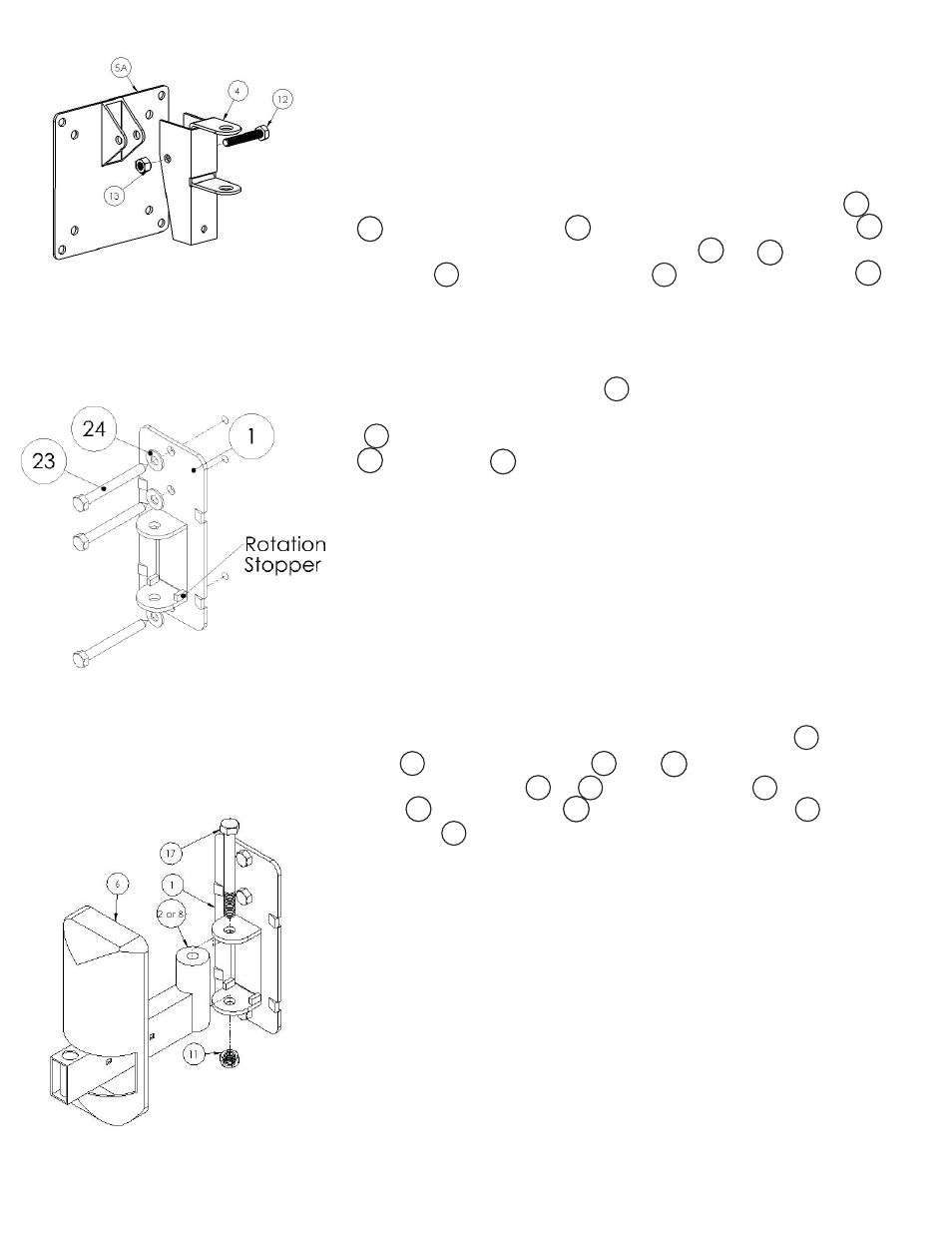
Step 1
Before starting, lay out all parts to your mount and match them to
the parts list provided. Verify that you have all your parts before
attempting to assemble the mount.
Step 2
Determine which VESA standard plate you will be using or
(75mm/100mm for or 200mm/100mmx200mm for
)
and attach the selected mounting plate or to the swivel
bracket using the M6 screw and the nylon nut .
(Set this assembly safely to the side for now.)
Step 3
Mark the wall or desired mounting surface in preparation of instal-
lation of wall mounting plate . If mounting to wooden studs,
pre drill pilot holes using a 7/32” drill bit. Attach the wall plate
to the wooden stud using the 5/16” by 2.5” long lag screw
and washer making sure the small rotation stoppers on the
wall plate are towards the bottom. WARNING: Please verify that
your mounting surface will support the combined weight of your
mount, mounting hardware, and fl at panel. Also verify that the
mounting surface is safe to drill through. Please note only mounting
hardware for mounting to wooden studs will be provided with the
unit. If mounting to a surface other than wooden studs then other
hardware will be required. If in doubt or uncertain about any of the
above, please contact a professional installer.
Step 4
Determine which arm confi guration you desire (double arm, single
arm, or near fl ush) and locate the correct arms. ( for near
fl ush, for single arm, and and for double arm.) Attach
the desired wall arm or to the wall plate using the 3/8”
screw , and nylon nut . Snap the plastic cover onto the
wall plate .
Step 2: Attaching the mount-
ing plate to the pivot bracket
(Mounting Plate A (#5A) shown)
Step 3: Attaching the wall plate
to the mounting surface
Step 4: Attaching the rear
force arm to the wall plate
3
2
11
17
2
8
1
5A
12
4
13
1
2
8
1
1
6
23
5B
5A
5B
5A
5B
24