Video Mount Products PDS-LCHB User Manual
Page 3
Step 1
Before starting, lay out all parts to your mount and match them to
the parts list provided. Verify that you have all your parts before
attempting to assemble the mount.
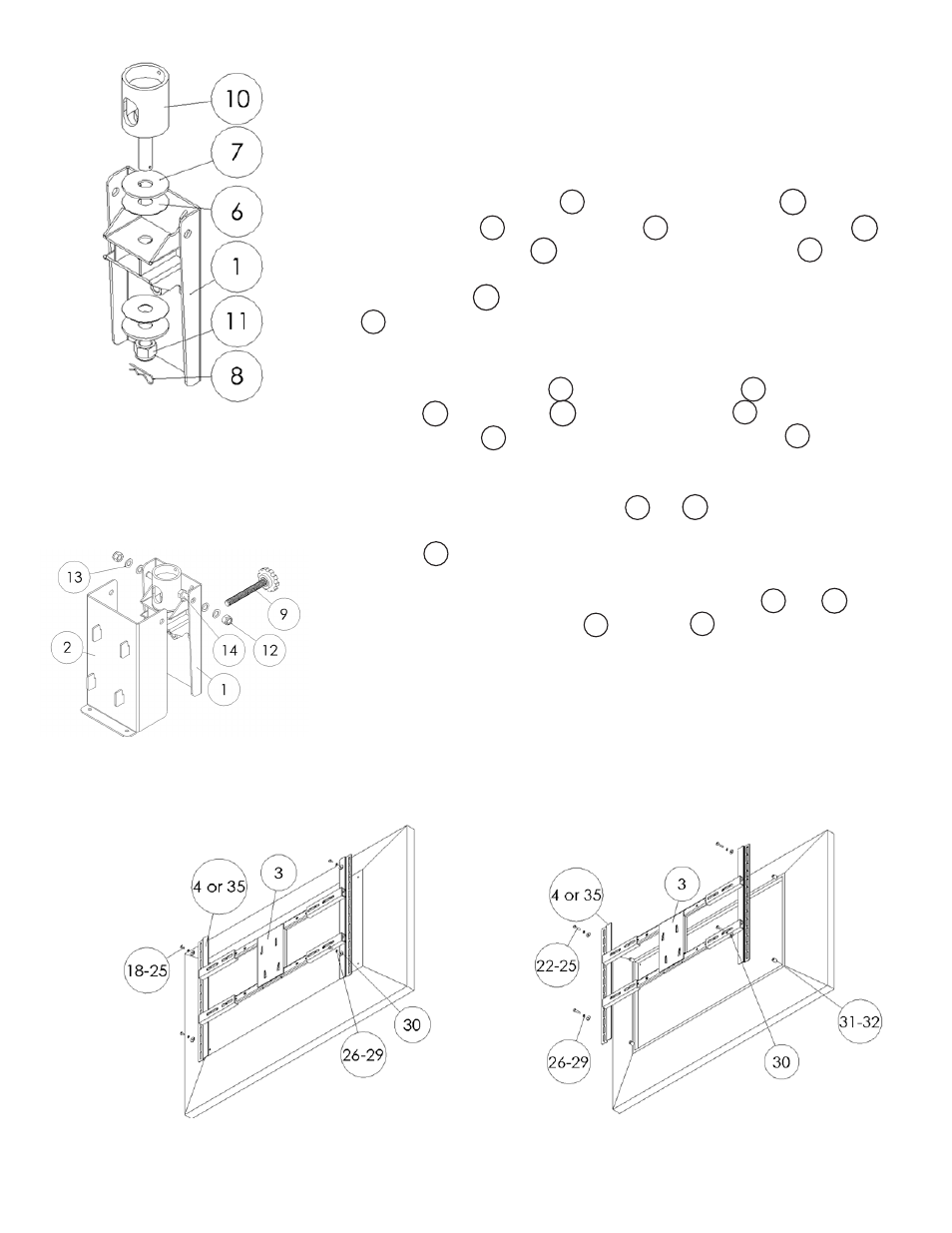
Step 2
Attach the Tilt Support
(#1)
to the Pipe Couple
(#10)
using the
Large Washers
(#7)
, PVC Washers
(#6)
and M16 Nylon Nut
(#11)
.
Once the Nylon Nut
(#11)
is tight, slide the Cotter Pin
(#8)
through
the small hole near the bottom of the screw coming out of the
Pipe Couple
(#10)
. Note: Be sure to tighten down the nylon nut
(#11)
as far as possible to prevent sag or list in the mount.
Step 3
Attach the Tilt Bracket
(#2)
to the Tilt Support
(#1)
using the M10
Screws
(#14)
, Washers
(#13)
and Nylon Nut
(#12)
. Insert the Ad-
justable Screw
(#9)
into the back of the Tilt Support
(#1)
.
Step 4
Determine which Mounting Rails
(#4
or
#35)
are most appropriate
for the size hole pattern that you have. Place those rails onto the H
Bracket
(#3)
and center the rails on the H Bracket. Determine the
correct screw size and if you need to use washers, lock washers, or
spacers. Secure the display to the Mounting Rail
(#4
or
#35)
using
the appropriate hardware
(#18
through
#32)
.
Step 2: Attaching the tilt
support to the pipe couple
SStep 3: Attaching the tilt
bracket to the tilt support
13
10
12
35
14
4
1
2
1
9
Step 4A: Attaching the flat panel to the
mounting rails (spacers not needed)
10
11
11
32
35
3
8
7
4
6
1
18
Step 4B: Attaching the flat panel to the
mounting rails (spacers used for recessed
hole pattern)
11