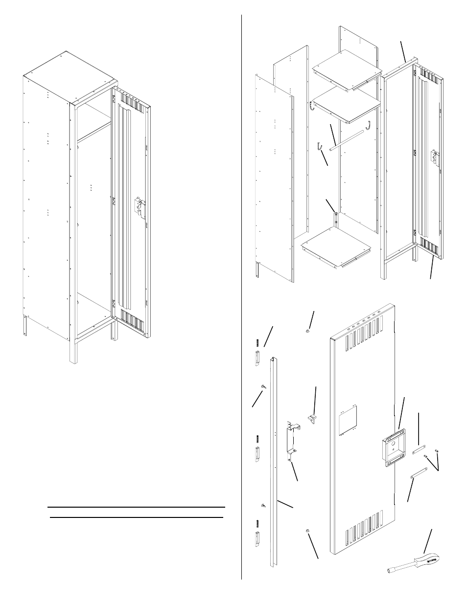
Figure 1, Door-lock detail – Tennsco Single Tier Lockers One Wide User Manual
Page 3
Care must be taken to assure that lockers
are set plumb and true before anchoring.
FIGURE 1
1
2
3
4
5
6
7
10
9
8
6
11
12
13
14
18
19
17
16
15
20
14
21
DOOR-LOCK DETAIL
8.
If joining units side by
side, temporarily install
only one bolt and nut in
the frame at the end of
unit.
9.
Stand units upright
and place in desired
location. Remove
temporary bolts in
frames and bolt
adjacent units
together through
frames.
NOTE: If the bolts
are not removed
before the frames
are joined side by
side, the frames will
have a 1/8" gap
between them.
10.
Place non-slotted end of coat rod (Ref. No. 10)
over projecting tab at top of left coat hook.
Slide the slotted end of the coat rod over the
projecting tab in the right coat hook and turn 90
degrees to secure it.
11.
Anchor units to wall or floor. The units are not
intended to stand free and may topple if not
secured. (Units standing back to back should
be bolted together.)
12.
If units are not pre-numbered, optional number
plates (Ref. No. 11) may be attached with two
#6 x 5/16 drive screws or push plugs (Ref. No.
12).