Handle/locking system installation instructions – Tennsco 2471 User Manual
Page 3
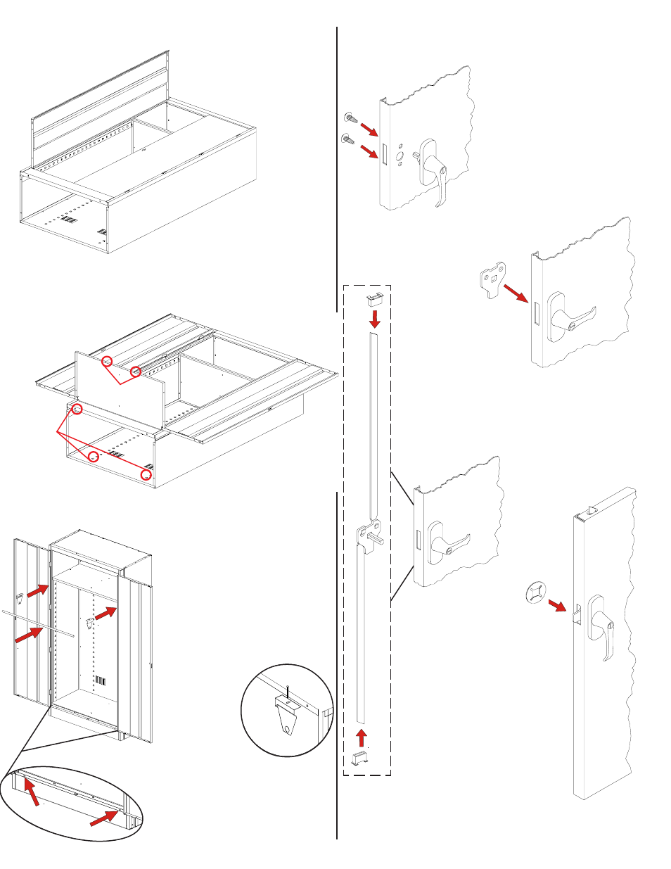
2.
Turn the handle to the
open position, and place
the locking cam (Ref. No. 12) over the
square shank of the door handle. The
latch must be facing
downward as shown.
10.
Attach the coat rod brackets
(Ref. No. 8) to the underside
of the shelf, inserting one bolt
and nut through the hole
provided on the far right and
far left side of the shelf. The
open side of each bracket
should face into the unit (see
below). Insert the coat rod
(Ref. No. 9) into
first one brack-
et, and then
into the other
by flexing the
second bracket.
1.
Place the locking handle (Ref. No. 11) on the
right hand door and
fasten with two #8-32 x
1/4 slotted bolts and
lockwashers (Ref. No. 16).
Handle/Locking System Installation Instructions
4.
Place the locking
cam retainer (Ref. No. 14)
over the square shank of
the door handle. Tap on
the edges of the cam
retainer with a hammer
until retainer sits firmly
against the locking cam.
3.
With the handle
still in the open
position, hook the locking bars (Ref.
No. 10) to the locking cam (see "A" at
left). Then, hold the lock bars in
position while sliding the nylon lock
bar guide inserts (Ref. No. 13) over
the lock bar ends
and through the
door slots (see "B"
at left).
B
B
8.
With the door & frame assembly in place, attach it
securely to the
unit by opening each door,
one at a time, and securing
the frame assembly using
2 bolts and 20 nuts
(Ref. Nos. 18
and 19). This
will require
attaching
nuts to the
nine pre-welded
studs along each
side, plus two bolts and
nuts along the top. The bottom
will attach to the frame in Step 9.
Leveler
Access
Holes
A
5.
Attach the "dummy"
handle (Ref. No. 15) to
the left door using two
#8-32 x 1/4 slotted
bolts and lockwashers
(Ref. No. 16).
9.
Place the bottom (Ref. No. 7) in the lowest notch
of the shelf adjusting strips on the sides and
back. Make sure the flange with two holes faces
the front, and that
it is over the flange of
the frame sill. If
necessary,
you may
push out on
the side walls to
enable the bottom to
more easily slide
into position. Attach the shelf
securely by bolting the bottom to the frame sill
with two bolts and nuts.
Two
holes
must
be in front.
11.
The cabinet must be level in order for the
doors to close properly. Levelers may
be adjusted by placing a screw-
driver through the hole in each
end of the sill and adjusting the
leveling screw.
Underside
of
Shelf
Left
Panel
of
Cabinet
In
se
rt
sh
elf
in
to
bo
tto
m
la
nc
es
.