Air exhaust, Between uses, Check valve servicing – SANDPIPER EB2-SM User Manual
Page 2: Diaphragm servicing, Caution
MODEL EB2-SM PAGE 2
520-097-000 8/00
creases cycling rate, but does not increase flow rate, cavitation has occurred, and
the valve should be closed slightly.
For the most efficient use of compressed air and the longest diaphragm life, throttle
the air inlet to the lowest cycling rate that does not reduce flow.
A NOTE ABOUT AIR VALVE LUBRICATION
The SandPiper pump’s pilot valve and main air valve assemblies are designed to
operate WITHOUT lubrication. This is the preferred mode of operation. There may be
instances of personal preference, or poor quality air supplies when lubrication of the
compressed air supply is required. The pump air system will operate with properly
lubricated compressed air supplies. Proper lubrication of the compressed air supply
would entail the use of an air line lubricator (available from Warren Rupp) set to
deliver one drop of 10 wt., non-detergent oil for every 20 SCFM of air the pump
consumed at its point of operation. Consult the pump’s published Performance Curve
to determine this.
It is important to remember to inspect the sleeve and spool set routinely. It should
move back and forth freely. This is most important when the air supply is lubricated.
If a lubricator is used, oil accumulation will, over time, collect any debris from the
compressed air. This can prevent the pump from operating properly.
Water in the compressed air supply can create problems such as icing or freezing
of the exhaust air causing the pump to cycle erratically, or stop operating. This can
be addressed by using a point of use air dryer to supplement a plant’s air drying
equipment. This device will remove excess water from the compressed air supply
and alleviate the icing or freezing problem.
AIR EXHAUST
If a diaphragm fails, the pumped liquid or fumes can enter the air end of the pump,
and be exhausted into the atmosphere. When pumping hazardous or toxic materials,
pipe the exhaust to an appropriate area for safe disposition.
This pump can be submerged if materials of construction are compatible with the
liquid. The air exhaust must be piped above the liquid level. Piping used for the air
exhaust must not be smaller than 1" (2.54 cm). Reducing the pipe size will restrict air
flow and reduce pump performance. When the product source is at a higher level
than the pump (flooded suction), pipe the exhaust higher than the product source to
prevent siphoning spills.
Freezing or icing of the air exhaust can occur under certain temperature and
humidity conditions. Use of an air dryer should eliminate most icing problems.
BETWEEN USES
When used for materials that tend to settle out or transform to solid form, the pump
should be completely flushed after each use, to prevent damage. Product remaining
in the pump between uses could dry out or settle out. This could cause problems with
valves and diaphragms at re-start. In freezing temperatures, the pump must be
drained between uses in all cases.
CHECK VALVE SERVICING
Need for inspection or service is usually indicated by poor priming, unstable cy-
cling, reduced performance or the pump’s cycling but not pumping.
Inspect the surfaces of both check valve and seat for wear or damage that could
prevent proper sealing. If pump is to prime properly, valves must seat air tight.
DIAPHRAGM SERVICING
Remove the eight bolts (four each side) securing the manifold assemblies to the
outer chambers. Remove the eight bolts securing the outer chamber to the inner
chamber. Remove the diaphragm assembly (outer plate, diaphragm, inner plate) by
turning the assembly counterclockwise using a 1" (2.54 cm) wrench on the outer
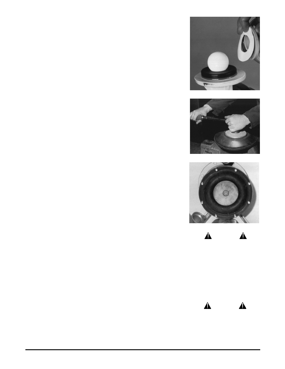
plate lugs. To disassemble the diaphragm assemblies, secure in a vise and turn the
outer plate counterclockwise using the 1” wrench.
Procedures for reassembling the diaphragms are the reverse of the above. The
diaphragms must be installed with their natural bulge to the outside, toward the outer
diaphragm plate. Install the inner plate with the flat face against the diaphragm.
After all components are in position in a vise and hand tight, tighten with a wrench
to approximately 40 ft. Ibs. (54.23 Newton meters) torque. After both diaphragm
assemblies have been assembled, thread one assembly into the shaft (hold the shaft
near the middle in a vise with soft jaws, to protect the finish). Install this sub assembly
Figure 2: Ball check valve and seat.
Figure 3: Torquing the diaphragm plate.
Figure 4: Installed diaphragm.
CAUTION
If a diaphragm fails the pumped product
or fumes can enter the air side of the
pump. This side is exhausted through
the exhaust port (muffler).
When the product is a hazardous or
toxic material, the exhaust should be
piped to an appropriate area for safe
disposition.
When the product source is at a higher
level than the pump (flooded suction),
the exhaust should be piped to a higher
level than the product to prevent spills
caused by siphoning.
CAUTION
Before maintenance or repair, shut off
the compressed air line, bleed the
pressure, and disconnect the air line
from the pump. The discharge line may
be pressurized and must be bled of its
pressure. When the pump is used for
toxic or aggressive fluids, it should be
flushed clean prior to disassembly.