Caution, Warning, Air inlet & priming – SANDPIPER PB1/2-A User Manual
Page 2: Air exhaust, Between uses, Check valve servicing, Diaphragm servicing
Model PB½
-A Type 3 Page 2
520-041-000 2/99
CAUTION
In the event of diaphragm rupture,
pumped material may enter the air end
of the pump, and be discharged into the
atmosphere. If pumping a product which
is hazardous or toxic, the air exhaust
must be piped to an appropriate area for
safe disposition.
WARNING
The weight of the air supply line and of
the filter must be supported by some
means other than the air valve cap.
Failure to provide support may result in
damage to the pump. A pressure
regulating valve should be installed to
prevent pressure from exceeding
recommended limits.
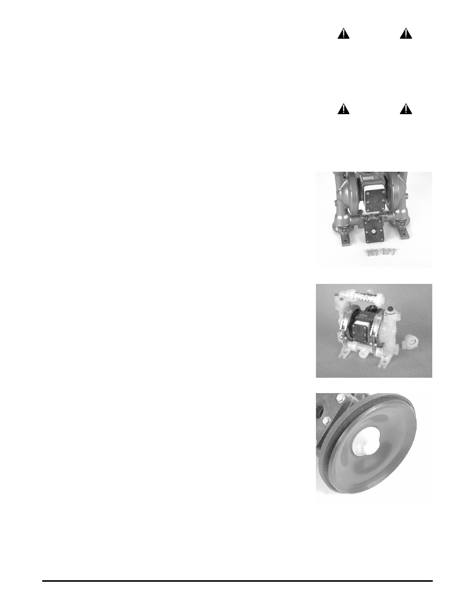
Figure 2: Exhaust cap assembly. (475-107-000)
Figure 3: Check valve and seat.
Figure 4: Diaphragm and diaphragm plate.
It is important to remember to inspect the sleeve and spool set routinely. It should
move back and forth freely. This is most important when the air supply is lubricated.
If a lubricator is used, oil accumulation will, over time, collect any debris from the
compressed air. This can prevent the pump from operating properly.
Water in the compressed air supply can create problems such as icing or freezing
of the exhaust air causing the pump to cycle erratically, or stop operating. This can be
addressed by using a point of use air dryer (available from Warren Rupp) to supple-
ment a plant’s air drying equipment. This device will remove excess water from the
compressed air supply and alleviate the icing or freezing problem.AIR SUPPLY
Air supply pressures cannot exceed 100 psi (6.89 bar). Connect the pump air inlet
to an air supply of sufficient capacity and pressure required for desired performance.
When the air line is solid piping, use a short length of flexible hose (not less than
3
¦
4
"
(19mm) in diameter) between pump and piping to eliminate strain to pipes.
AIR INLET & PRIMING
For start-up, open an air valve approximately
1
¦
2
to
3
¦
4
turn. After the unit primes, an
air valve can be opened to increase flow as desired. If opening the valve increases
cycling rate, but does not increase flow rate, cavitation has occurred, and the valve
should be closed slightly.
For the most efficient use of compressed air and the longest diaphragm life, throttle
the air inlet to the lowest cycling rate that does not reduce flow.
AIR EXHAUST
If a diaphragm fails, the pumped liquid or fumes can enter the air end of the pump,
and be exhausted into the atmosphere. When pumping hazardous or toxic materials,
pipe the exhaust to an appropriate area for safe disposition.
This pump can be submerged if materials of construction are compatible with the
liquid. The air exhaust must be piped above the liquid level. Piping used for the air
exhaust must not be smaller than 3/8" (.9525 cm). Reducing the pipe size will restrict
air flow and reduce pump performance. When the product source is at a higher level
than the pump (flooded suction), pipe the exhaust higher than the product source to
prevent siphoning spills. Use exhaust kit 475-107-000 to pipe out exhaust.
Freezing or icing of the air exhaust can occur under certain temperature and
humidity conditions. Use of a Warren Rupp Air Dryer unit should eliminate most icing
problems.
BETWEEN USES
When used for materials that tend to settle out or transform to solid form, the pump
should be completely flushed after each use, to prevent damage. Product remaining
in the pump between uses could dry out or settle out. This could cause problems with
valves and diaphragms at re-start. In freezing temperatures, the pump must be
drained between uses in all cases.
CHECK VALVE SERVICING
Need for inspection or service is usually indicated by poor priming, unstable cy-
cling, reduced performance or the pump’s cycling but not pumping.
Remove the twelve capscrews securing the manifold assemblies to the outer
chambers. Inspect the surfaces of both check valve and seat for wear or damage that
could prevent proper sealing. If pump is to prime properly, valves must seat air tight.
DIAPHRAGM SERVICING
Remove the two V-Band clamps securing the outer chambers to the intermediate
housing. Remove the diaphragm assembly (outer plate, diaphragm, inner plate) by
turning the assembly counterclockwise using a
3
/
4
" (1.91 cm) wrench on the outer
plate lugs. (If a socket is used, it must be a six point socket.) The interior components
consisting of the shaft seal and pilot valve assembly are now accessible for service.
Procedures for reassembling the diaphragms are the reverse of the above. During
reassembly make certain that the rubber bumper is on the rod on each side. Install
the diaphragm with the natural bulge outward.
Install the outer diaphragm plate on the outside of the diaphragm and make cer-
tain that the large radius side of the inner plate is toward the diaphragm. Tighten the
outer diaphragm plate to approximately 90 in. lbs. (10.16 Newton meters).
Torque while allowing the diaphragm to turn freely with plates. Use a wrench on
the outer diaphragm plate of the opposite side to keep rod from rotating. If the oppo-
site chamber is assembled, the rod need not be held.