Models with suction/discharge less than 1, Pilot valve actuator, Troubleshooting – SANDPIPER PB3/4-A User Manual
Page 3: Caution
520-121-000 7/99
Model PB¾
-A Type 3 Page 3
of the exhaust air causing the pump to cycle erratically, or stop operating. This can
be addressed by using a point of use air dryer available from Warren Rupp) to
supplement a plant’s air drying equipment. This device will remove excess water
from the compressed air supply and alleviate the icing or freezing problem.
ESADS: EXTERNALLY SERVICEABLE AIR DISTRIBUTION
SYSTEM
Please refer to the exploded view drawing and parts list in the Service Manual
supplied with your pump. If you need replacement or additional copies, contact your
local Warren Rupp Distributor. or the Warren Rupp factory Literature Department at
the number shown below To receive the correct manual, you must specify the
MODEL and TYPE information found on the name plate of the pump.
MODELS WITH SUCTION/DISCHARGE LESS THAN 1"
The main air valve sleeve and spool set is located in the valve body mounted on
the pump with four hex head capscrews. The valve body assembIy is removed from
the pump by removing these four hex head capscrews.
With the valve body assembly off the pump, access to the sleeve and spooI set is
made by removing a retaining ring (each end) securing the end cap on the valve
body assembly. With the end caps removed, slide the spool back and forth in the
sleeve. The spool is closely sized to the sleeve and must move freely to allow for
proper pump operation. An accumulation of oil, dirt or other contaminants from the
pump’s air supply, or from a failed diaphragm, may prevent the spool from moving
freely. This can cause the spool to stick in a position that prevents the pump from
operating. If this is the case, the sleeve and spool set should be removed from the
valve body for cleaning and further inspection.
Remove the spool from the sleeve. Using an arbor press or bench vise (with an
improvised mandrel), press the sleeve from the valve body. Take care not to dam-
age the sleeve. At his point. inspect the o-rings on the sleeve for nicks, tears or
abrasions. Damage of this sort could happen during assembly or servicing. A sheared
or cut o-ring can allow the pump’s compressed air suppiy to leak or bypass within the
air valve assembly, causing the pump to leak compressed air from the pump air
exhaust or not cycle properly. This is most noticeable at pump dead head or high
discharge pressure conditions. Replace any of these o-rings as required or set up a
routine, preventive maintenance schedule to do so on a regular basis. This practice
should include cleaning the spool and sleeve components with a safety solvent or
equivalent, inspecting for signs of wear or damage, and replacing worn components.
To re-install the sleeve and spool set, Iightly lubricate the o-rings on the sleeve
with an o-ring assembly lubricant or lightweignt oil (such as 10 wt. air line lubricant).
Press the set into the valve body easily, without shearing the o-rings. Re-install one
end cap, and retaining ring on the valve body. Using the arbor press or bench vise
that was used in disassembly, press the sleeve back into the valve body. Re-install
the spool, keeping the counter-bored end toward you, and install the spring, oppo-
site end cap and retaining ring on the valve body. After inspecting and cleaning the
gasket surfaces on the valve body and intermediate, re-install the valve body on the
pump using new gaskets. Tighten the four hex head capscrews evenly and in an
alternating cross pattern, at 70 in./lbs. (7.9 Newton meters).
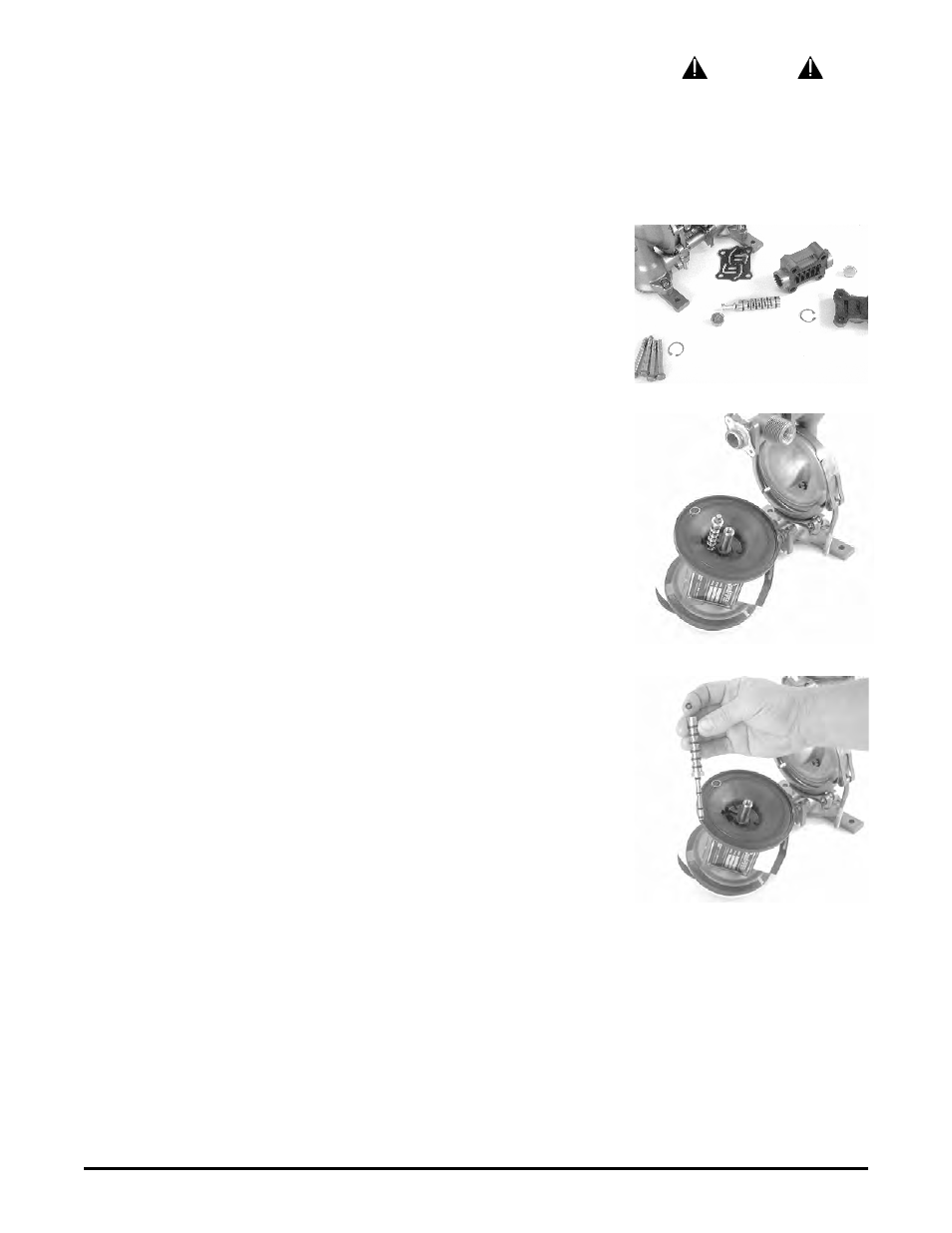
PILOT VALVE ACTUATOR
The pilot valve spool (item 9C) contains 6 o-rings (item 9D). This spool moves
through the sleeve (item 9B). Check condition of o-rings for cuts or gouges before re-
assembly. Apply a light coating of grease to the o-rings when inserting into the
sleeve. Insert spool into sleeve from chamfered side. The o-ring on the end should
be installed after the spool is in place (install last). Make sure the sleeve is locked
into the intermediate bracket (item 16) with retainer ring ( item 9E). Fig. 7.
TROUBLESHOOTING
1. Pump wlll not cycle
A. Check to make sure the unit has enough pressure to operate and that the air inlet
valve is open.
B. Check the discharge line to insure that the discharge line is neither closed nor
blocked.
C. If the spool in the air distribution valve is not shifting, check the main spool. It must
slide freely.
D. Excessive air leakage in the pump can prevent cycling. This condition will be
CAUTION
Before maintenance or repair, shut off
the compressed air line, bleed the
pressure, and disconnect the air line
from the pump. The discharge line may
be pressurized and must be bled of its
pressure. When used for toxic or
aggressive fluids, the pump should
always be flushed clean prior to
disassembly.
Figure 5: Sleeve and spool set.
Figure 6: Disassembling the pilot valve.
Figure 7: Pilot valve with o-rings.