Intermediate assembly drawing – SANDPIPER T30 User Manual
Page 15
t30mdl1sm-rev0614
sandpiperpump
.
com
Model T30 Metallic •
12
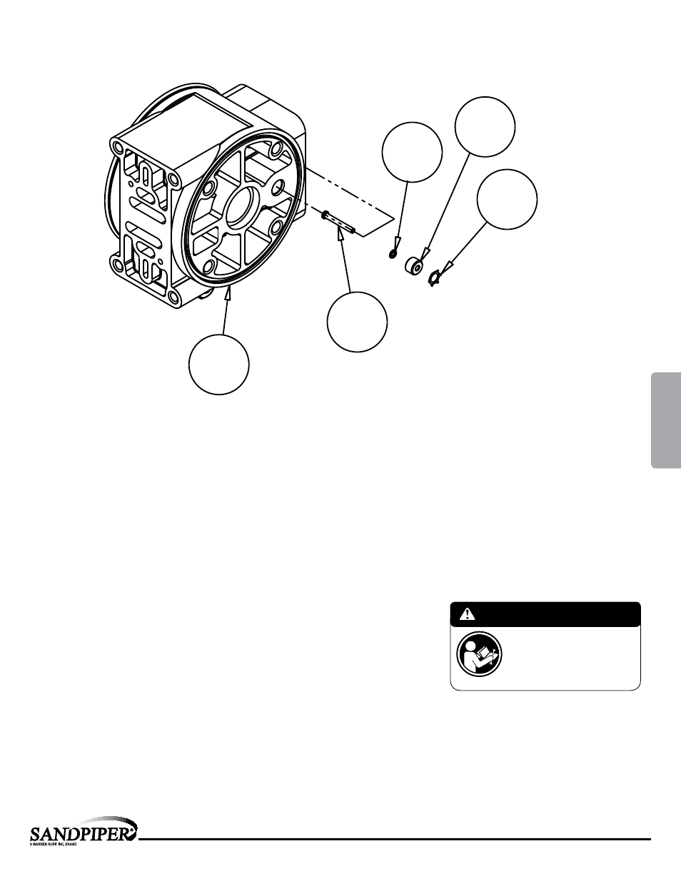
Intermediate Assembly Drawing
Intermediate Repair Parts List
Item
Part Number
Description
Qty
5
114.024.313
Bracket, Intermediate
1
114.024.110
Bracket, Intermediate
1
7
135.034.506
Bushing, Plunger
2
26 560.001.360 O-Ring
2
30
620.020.115
Plunger, Actuator
2
31
675.042.115
Ring, Retaining*
2
33
720.004.360
Seal, Diaphragm Rod
2
*Note: It is recommended that when plunger components
are serviced, new retaining rings be installed.
Intermediate Assembly Drawing
Step 1: Remove plunger, actuator (30) from center of
intermediate pilot valve cavity.
Step 2: Remove Ring, Retaining (31), discard.
Step 3: Remove bushing, plunger (7), inspect for wear
and replace if necessary with genuine parts.
Step 4: Remove O-Ring (26), inspect for wear and
replace if necessary with genuine parts.
Step 5: Lightly lubricate O-Ring (26) and insert into
intermediate.
Step 6: Reassemble in reverse order.
Step 7: Remove Seal, Diaphragm Rod (33).
Step 8: Clean seal area, lightly lubricate and install new Seal,
Diaphragm Rod (33).
IMPORTANT
When the pumped product source is at a higher
level than the pump (flooded suction condition),
pipe the exhaust higher than the product source
to prevent siphoning spills. In the event of a
diaphragm failure a complete rebuild of the
center section is recommended.
26
7
31
30
5
MODEL SPECIFIC
4: AIR
END