Reassembly, Warranty, Permanent installations – SANDPIPER SMA3-A User Manual
Page 2
Warren Rupp, Inc. A Unit of IDEX Corporation P.O. Box 1568 Mansfield, Ohio 44901-1568 USA (419) 524-8388 Fax (419) 522-7867 • www.warrenrupp.com
Remove strainer assembly secured with four cap nuts. Impeller is removed by
inserting block of wood, hammer handle, or similar object between impeller vane and
pump casing (see Figure 2) to prevent rotation and turn shaft counterclockwise from
air motor end with drift pin inserted through hole in shaft. Remove shaft assembly
from volute casing by removing snap ring above oil seal, bump shaft and bearing from
casing. Rotating portion of shaft seal can now be removed from shaft and stationary
seal seat can be removed from casing.
REASSEMBLY
When installing shaft seal on shaft use a lightweight oil and locate seal at extreme
end of shaft so that carbon face of seal will contact seal seat before bearing enters
housing bore during assembly. This eliminates the possibility of carbon washer falling
out of position in seal cage while bumping shaft and bearing assembly into correct
position. Push oil seal and retainer into bore above bearing and install snap ring. Install
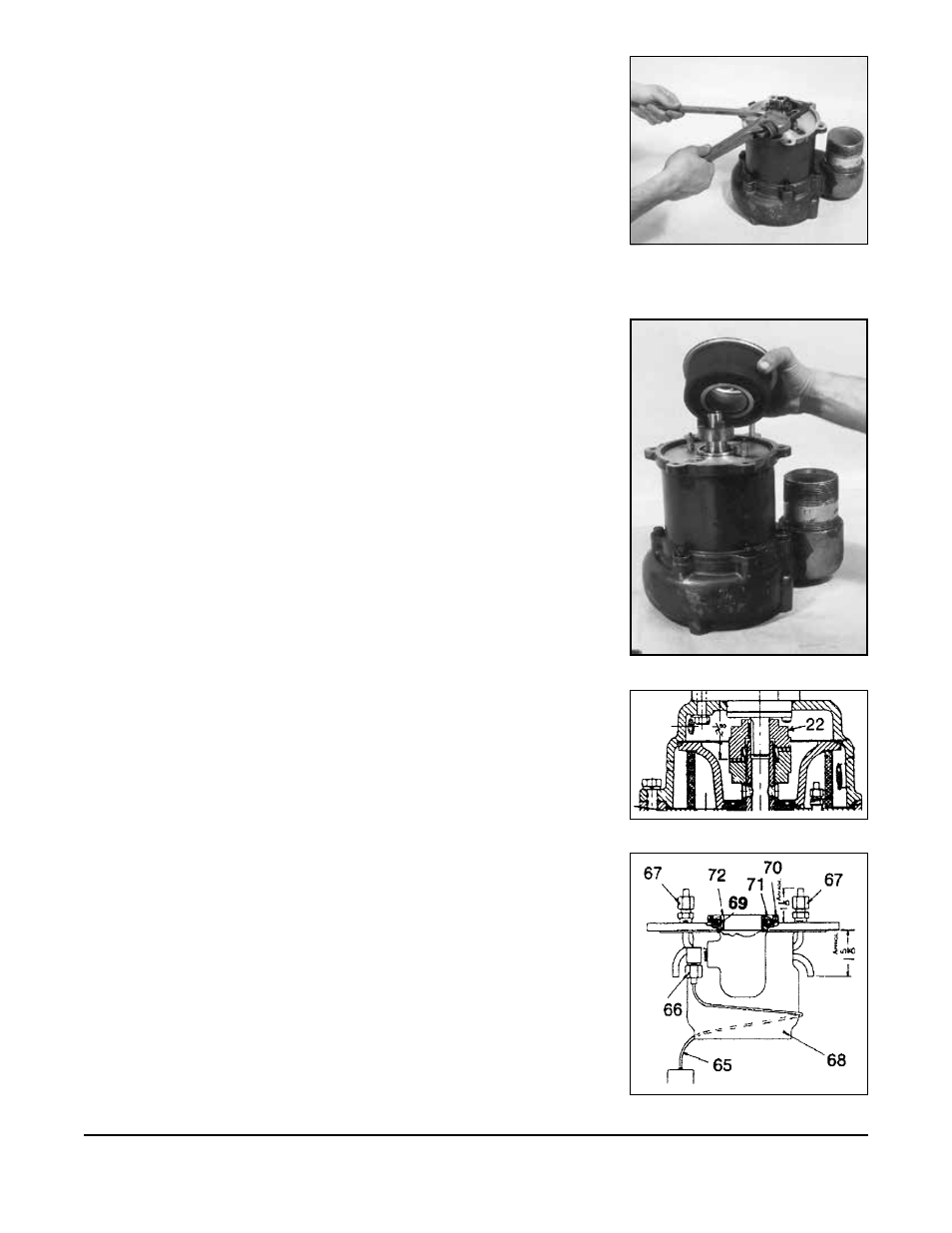
governor weights, spool and spring if removed. Lay o-ring into casing bore and install
intermediate housing. Install o-ring and drop governor housing into position and push
down into place. Slide sleeve and spacer onto shaft with spacer and shaft holes in
alignment. Install coupling and tighten securely with drift pin and pipe wrench with
same procedure as removal. (See Figure 3.) Insert o-ring into filter housing bore and
press filter element and housing into position as shown. (See Figure 4.) Install o-ring
into intermediate bore and o-ring on to counter bore at upper end of filter housing.
Assembly is now ready to receive air motor and housing assembly. If coupling half
on air motor shaft is removed, make certain coupling is relocated to correct posi-
tion as indicated dimensionally in Figure 5. Line up coupling jaws for engagement
by using bolt holes of castings as a reference. Rubber spider should be installed in
lower coupling half. Lower air motor and housing into place slowly to feel for correct
coupling engagement. When coupling is properly engaged, assembly can be pushed
down by hand.
DO NOT FORCE ASSEMBLY TOGETHER WITH BOLTS. If air motor
assembly is lifted back up in attempting to engage blind coupling, make certain that
o-ring on top end of filter housing is still in position. If o-ring is out of position during
this blind assembly, air will by-pass the governor and over-speeding can occur. Fill
with recommended oil and run unit without pumping to check for possible oil leakage
at shaft seal or o-ring joints. Turn air supply on slowly to make certain that governor
is operating properly.
WARRANTY
This unit is guaranteed for a period of five years against defective material and
workmanship.
PERMANENT INSTALLATIONS
NOTE: As mentioned, the SMA3-A pump does require that oil be in the reservoir
for bearing and motor lubrication. For permanent installations remove item 66, then
plug the hole with a
1
/
8
" pipe plug, part number 618-002-330. Fill the reservoir and
make sure that an in-line oiler (type oil as recommended) is used in the air supply to
the pump. Set lubricator at a usage rate of 1 pint (473 cc) every 50 hours. The motor
will then be lubricated by the in-line oiler and the bearing by the oil in the reservoir.
Figure 3
Figure 4
Figure 5
Figure 6
sma3dl1sm-REV0714
Model SMA3-A Page 2