Getting to know your lathe assembly – RIKON Power Tools 70-500 User Manual
Page 6
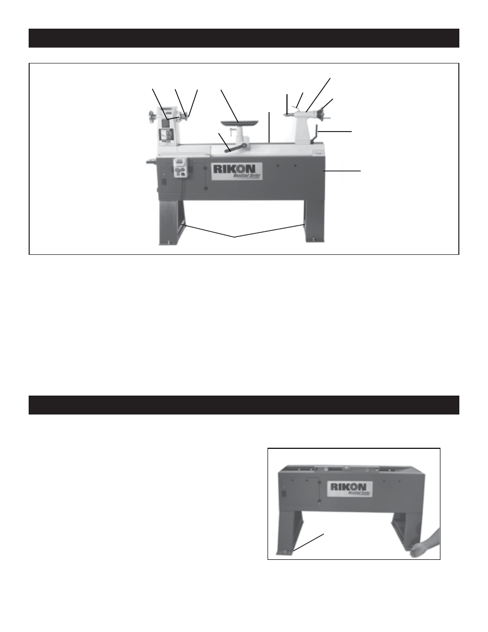
Item Description
1
Stand Legs
2
Stand Body
3
Lathe bed
4
Face plate
5
Spur center
6
Tool rest
7
Live center
8
Tail stock
6
Item Description
9
Tailstock handwheel
10
Tailstock spindle locking arm
11
Tool rest base
12
Spindle lock
13
Tailstock locking lever
14
Tool rest seat locking lever
The machine must not be plugged in and the power switch must be in the OFF position until assembly is
complete.
Determine Lathe Location in
Workshop
Find a location in the workshop that is level and
has adequate lighting. Make sure that there is
plenty of room between the lathe and other
machines. Place the lathe in an area that will
support its weight and is close to a power source.
Getting to Know Your Lathe
Assembly
Fig.01
Leveling Feet
2
1
4
5
6
3
7 10
9
13
14
12
8
See also other documents in the category RIKON Power Tools Power Tools:
- 10-201 (40 pages)
- 10-305 (24 pages)
- 10-308 (20 pages)
- 10-315 (28 pages)
- 10-321 (52 pages)
- 10-325 (28 pages)
- 10-346 (38 pages)
- 10-350 (32 pages)
- 10-370 (34 pages)
- 10-600VS (17 pages)
- 23-400 (22 pages)
- 23-400H (28 pages)
- 25-010 (26 pages)
- 25-010H (32 pages)
- 25-200 (26 pages)
- 25-200H (36 pages)
- 30-100 (24 pages)
- 30-120 (20 pages)
- 30-140 (21 pages)
- 30-240 (22 pages)
- 30-251 (21 pages)
- 34-250 (18 pages)
- 50-112 (18 pages)
- 50-120 (18 pages)
- 50-142 (24 pages)
- 50-150 (18 pages)
- 51-200 (14 pages)
- 60-100 (16 pages)
- 60-200 (16 pages)
- 61-200 (16 pages)
- 61-1250 (18 pages)
- 61-1600 (18 pages)
- 61-2400 (18 pages)
- 62-100 (16 pages)
- 63-100 (16 pages)
- 70-050 (16 pages)
- 70-100 (18 pages)
- 70-300 (28 pages)
- 70-425 (18 pages)
- 80-805 (22 pages)
- 10-110 (27 pages)
- 10-300 (17 pages)
- 10-320 (22 pages)
- 10-340 (22 pages)