Adjustments and operations – RIKON Power Tools 70-500 User Manual
Page 10
Adjusting Tailstock
Loosen cam lever (A-Fig. 21) to move the tailstock
along the lathe bed to desired position. Tighten
lever.
To adjust tailstock ram in or out, loosen locking arm
(B-Fig. 21) and turn handwheel (C-Fig. 21). When
the tailstock ram is in a desired position, tighten
locking arm. Figure 21
The tailstock ram will travel from 0” to 4”.
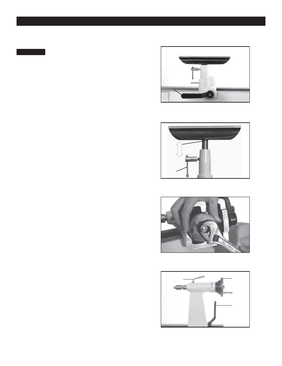
Adjusting the Tool Rest
Do not adjust tool rest or tool rest
base while the lathe is turned on. Make sure lathe
is turned off and that the work piece comes to a
complete stop before making adjustments.
The tool rest base (A-Fig. 18) can be easily moved
along the lathe bed. Loosen cam lever (B-Fig. 18)
counter clockwise, slide tool rest base to new
position, and tighten cam lever clockwise.
To adjust the height of the tool rest, loosen locking
arm (A-Fig. 19), raise or lower tool rest, tighten
locking arm.
Note: Position the tool rest 1/4” to the workpiece.
Rotate workpiece by hand to check for clearance.
The tool rest should also be 1/8” above the
centerline of the workpiece. (Figure 19)
Adjustments and Operations
10
A
B
To adjust clamping action of the tool rest base,
remove base and adjust nut clockwise to tighten
and counterclockwise to loosen. (Figure 20)
Warning:
To adjust clamping action of the tailstock, remove it
from lathe bed and adjust nut clockwise to tighten
and counterclockwise to loosen. (See Fig.20)
Fig.18
C
A
B
A
Fig.19
Fig.20
Fig.21