RIKON Power Tools 70-500 User Manual
Page 15
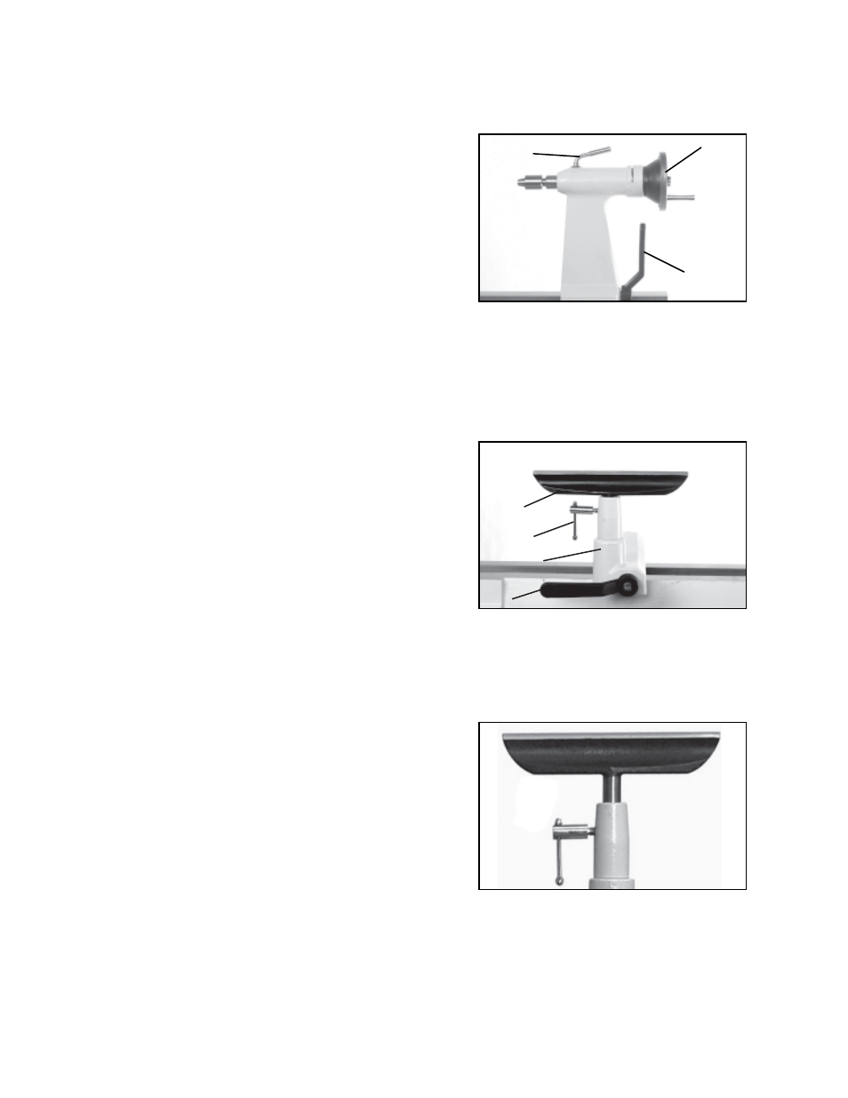
TAILSTOCK
The tailstock can be moved along the bed ways
and locked by way of the cam lever (A-Fig 35).
Excessive pressure should be avoided.
The sliding spindle (ram) is hollow to allow for long
hole drilling as well as having a MT-2 taper which
accepts the live center and other tapered acces-
sory tools. The spindle is moved by winding the the
large handwheel (B-Fig. 35) and can be tightened
by the locking arm (C-Fig. 35).
CAM-LOCK TOOLREST BASE
The cam-lock toolrest base (A-Fig. 36) is designed
as a quick action easy to use support base for the
toolrest (B-Fig.36).
Locking and unlocking is by way of the cam lever
(C-Fig 36) which will operate in either direction.
Excessive pressure when locking should be
avoided.
The toolrest locking arm (D-Fig.36) is positioned
for ease of use. Excessive pressure should be
avoided.
A
B
D
C
TOOLREST
The toolrest has been specially shaped for opera-
tor safety and ease of use. The top face has been
machined to assist smooth tool movement. If this
surface becomes damaged from sharp edged
tools, use a fine file to make smooth. (Figure 37)
Note: Position the tool rest as close to the work
piece as possible. It should be 1/8” above the
centerline of the workpiece.
15
Fig.35
A
B
C
Fig.36
Fig.37