Maintenance, Indexing/spindle lock, Fig.16 fig.17 – RIKON Power Tools 70-050 User Manual
Page 9
9
Typical Operations
The lathe is set up for a typical spindle turning
operation.(See Fig.12)
The lathe can be set up for a faceplate turning
operation. The work piece should be “rough cut”
as close as possible to finished shape before
mounting. (See Fig.12)
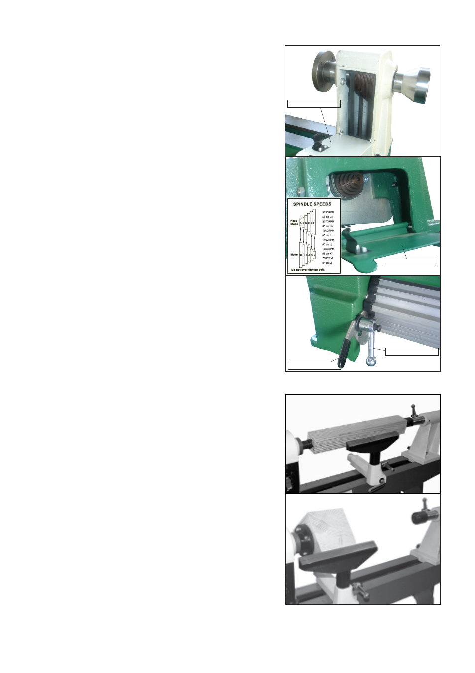
Changing Spindle Speeds
The lathe features a six step motor and spindle
pulleys to provide different spindle speeds. The
lathe Model#70-050VS features a three step mo-
tor and spindle pulleys to provide different spindle
speeds.
With access covers open, loosen locking arm.
Raise lever to release tension on motor pulley
and tighten locking arm. Check speed and belt
position chart inside access cover to determine
spindle speed required.
Move drive belt to desired pulley combination.
Loosen locking arm, lower lever, and the motor
will provide proper tension on the drive belt. Tight-
en locking arm and close access covers.
(See Fig.11)
Tension Lever
Locking arm
Access cover
Access cover
Fig.11
CAUTION! BEFORE CLEANING OR CARRYING OUT MAINTENANCE WORK, DISCONNECT
THE MACHINE FROM THE POWER SOURCE (WALL SOCKET). NEVER USE WATER OR
OTHER LIQUIDS TO CLEAN THE MACHINE. USE A BRUSH. REGULAR MAINTENANCE OF THE
MACHINE WILL PREVENT UNNECESSARY PROBLEMS.
Keep the lathe bed casting clean and lubricated.
Keep the outside of the machine clean to ensure accurate operation of all moving parts and prevent
excessive wear.
Keep the ventilation slots of the motor clean to prevent it from overheating.
Remove all saw dust and chips from the lathe after each use.
10
The lathe can be set up for a faceplate turning
operation. The work piece should be “rough
cut” as close as possible to finished shape
before mounting. (See Fig.16)
Indexing/Spindle Lock
The dual purpose indexing/spindle lock is
positioned on the top of the headstock for ease of
use. The headstock indexing feature has 12 equally
spaced positions. The spring loaded locking pin
assembly is engaged by turning the knob a half turn
allowing it to drop into the desired position. To
disengage, lift the lock knob up and turn a half turn
either direction. (See Fig.17 & Fig.18)
The 12 position indexing feature allows accurate
pattern work on projects such as straight fluting,
grooving, drilling, lay out and more. This feature
also allows the user to lock the spindle for
removing face plates, chucks and other
accessories without needing two tools.
To use the spindle lock, disengage the locking pin
by lifting up and rotating a half turn. The pin will
engage in the closest pin available. Once locked
an accessory such as a face plate can be removed
with the wrench supplied.
Fig.18
Maintenance
Fig.16
Fig.17
Fig.12