Getting to know your lathe assembly, Installing tool rest and base on lathe bed – RIKON Power Tools 70-050 User Manual
Page 6
6
The machine must not be plugged in and the power switch must be in the OFF position until assembly
is complete.
Installing Tool Rest and Base On Lathe
Bed
Remove the tailstock assembly by releasing the
locking handle and sliding the assembly off the
end of the lathe bed.
Slide the tool rest base onto the lathe bed and
reinstall the tailstock assembly.
Loosen locking arm and insert tool rest into tool
rest base, adjust height up or down and tighten
locking arm. (See Fig.01)
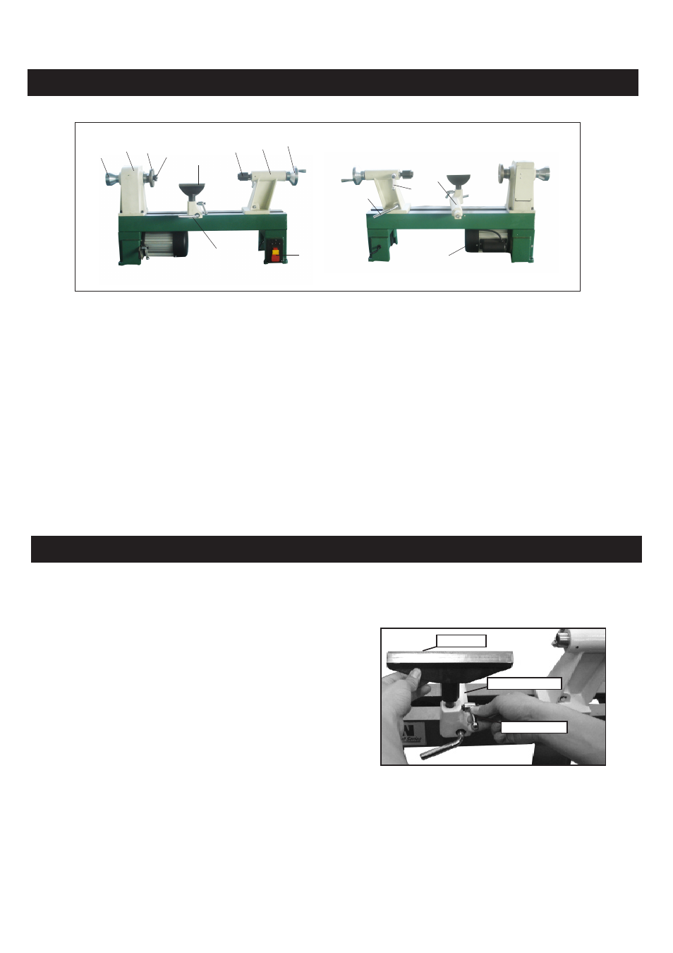
Getting to Know Your Lathe
Assembly
Locking arm
Tool rest
Tool rest base
Fig.01
1
2
3 4
5
6
7
8
9
10
11
12
13
14
Item Description
1 Handwheel
2 Headstock
3 Face plate
4 Spur center
5 Tool rest
6 Live center
7 Tailstock
Item Description
8 Tailstock handwheel
9 Switch
10 Tool rest seat locking lever
11 Tailstock locking lever
12 Tailstock spindle locking arm
13 Tool rest base
14 Motor
- 10-201 (40 pages)
- 10-305 (24 pages)
- 10-308 (20 pages)
- 10-315 (28 pages)
- 10-321 (52 pages)
- 10-325 (28 pages)
- 10-346 (38 pages)
- 10-350 (32 pages)
- 10-370 (34 pages)
- 10-600VS (17 pages)
- 23-400 (22 pages)
- 23-400H (28 pages)
- 25-010 (26 pages)
- 25-010H (32 pages)
- 25-200 (26 pages)
- 25-200H (36 pages)
- 30-100 (24 pages)
- 30-120 (20 pages)
- 30-140 (21 pages)
- 30-240 (22 pages)
- 30-251 (21 pages)
- 34-250 (18 pages)
- 50-112 (18 pages)
- 50-120 (18 pages)
- 50-142 (24 pages)
- 50-150 (18 pages)
- 51-200 (14 pages)
- 60-100 (16 pages)
- 60-200 (16 pages)
- 61-200 (16 pages)
- 61-1250 (18 pages)
- 61-1600 (18 pages)
- 61-2400 (18 pages)
- 62-100 (16 pages)
- 63-100 (16 pages)
- 70-100 (18 pages)
- 70-300 (28 pages)
- 70-425 (18 pages)
- 70-500 (28 pages)
- 80-805 (22 pages)
- 10-110 (27 pages)
- 10-300 (17 pages)
- 10-320 (22 pages)
- 10-340 (22 pages)