Operation – RIKON Power Tools 51-200 User Manual
Page 7
7
Fig. 06
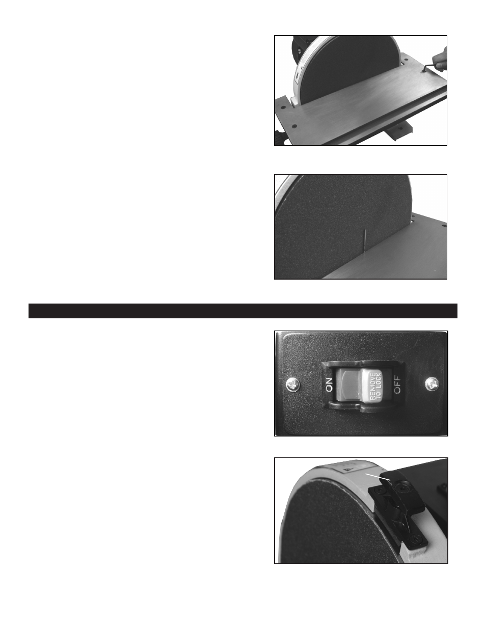
Fig. 07
Fig. 05
Fig. 04
Warning: To avoid jamming the workpiece or fingers
between the table and sanding surface, the table
edge should be a maximum of 1/16 inch from sanding
surface.
3. Always maintain a gap of approximately 1/16”
between the table edge, and disc. If adjustment is
necessary loosen the four bolts (Fig. 04) and move
the table into position.
4. Use a 1/16 inch drill bit as a spacer. Place the
drill bit between the disc and the inside edge of the
table. Hold the table against the 1/16 inch drill bit and
tighten the four hex bolts. (See Fig. 05)
Show similar with correct sander
On/Off Switch
The On/Off Locking Switch needs to have the
switch key inserted before the switch can be used
(key located in parts bag). This feature prevents
unauthorized use of the sander. (See Fig. 06)
CAUTION: Never walk away from sander when
machine is running. Always lock the switch in the Off
position and unplug from the power supply when not
in use.
Operation
Disc Brake
Warning: Never apply the disc brake with the switch
in the “ON” position. Damage to the brake or disc may
occur.
This 12” Disc Sander is equipped with a manual disc
brake which can be applied by pressing down on
brake lever
(Fig. 07)
, after the switch has been turned
off.
1
4
1
3
2
Brake Lever