Adjustments, Fig. 29 – RIKON Power Tools 25-010H User Manual
Page 16
16
ADJUSTING THE CUTTERHEAD
The Cutterhead that holds the knife inserts is fastened to
the machine’s cabinet, and is not adjustable. Based on
the postion of this main component of the machine, all of
the other parts - rollers and tables - are then pre-set by
the factory to align with the cutterhead. Should any of the
tables or rollers get out of parallel with the cutterhead, they
can be adjusted separately following the instructions in this
manual.
ADJUSTMENTS
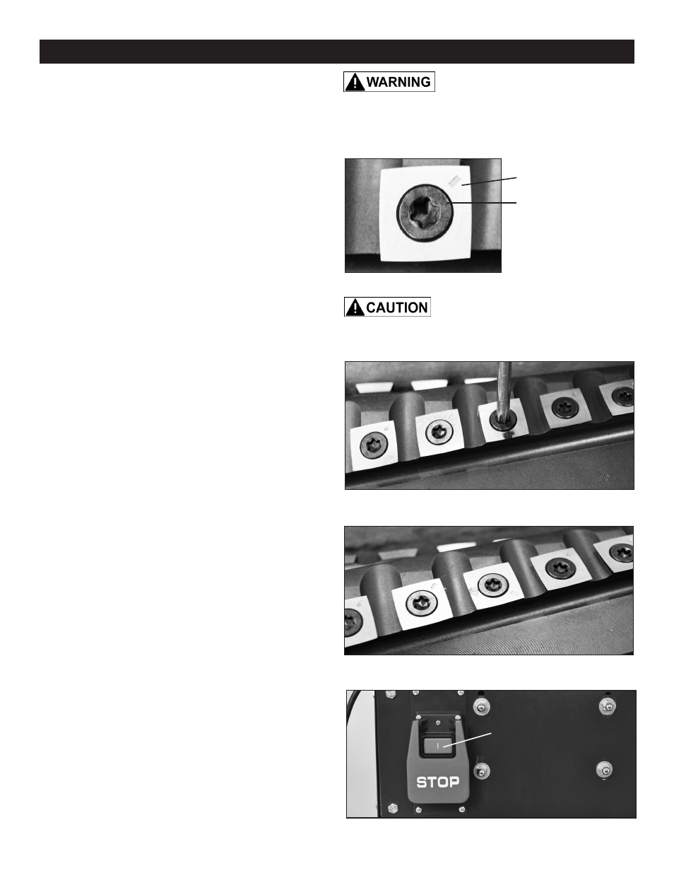
ROTATING OR REPLACING KNIFE INSERTS
This machine has a helical cutterhead with four rows of
carbide knife inserts. Each of the 44 inserts on the
cutterhead are indexed and have four sharpened sides.
If the knives become dull, or one becomes nicked, simply
loosen the retaining screws with the supplied star head
screwdriver, lift up and rotate the inserts to a new sharp-
ened edge. No setting is required, as the cutterhead has
been machined to automatically index and set the inserts in
proper position for use. When all four sides of an insert are
dull, the insert can be easily removed and a new carbide
insert placed in the location. To rotate or remove an insert:
1. Unplug power cable.
2. Remove the Screw (#193), that holds the Insert in the
cutterhead, and the Insert knife (#192). FIG. 26.
3. While the insert is removed, clean any resin buildup or
trapped dust from the surfaces of the cutterhead with a
suitable solvent. A tooth brush works well for safe cleaning
around the sharp inserts. Any accumulated dust can affect
the seating of the insert in the cutterhead.
4. Rotate the insert so that a new sharpened edge is in
position. The inserts have a indication mark on their top
surface corner, so that you can reference the positioning of
the insert's dulled or sharpened edges. FIG. 26, 27, 28.
5. Tighten the insert's set screw to lock the insert back in
position. DO NOT overtighten the screw or damage to the
insert may result. Torque to 50-55 in/lbs.
6. Plug in the power cable when you are ready to
resume jointing and planing.
THE MACHINE MUST NOT BE
PLUGGED IN AND THE POWER SWITCH MUST BE IN
THE OFF POSITION UNTIL ALL ADJUSTMENTS ARE
COMPLETE.
FIG. 27
FIG. 28
FIG. 26
CARBIDE INSERT
KNIFE HAS 4
SHARP EDGES
INDEX MARK
STAR HEAD
SET SCREW
Wear gloves when changing knife
inserts to avoid the risk of personal injury by cuts that may
result from touching the sharp edges!
ON/OFF SWITCH
The planer is equipped with a standard, push button ON/
OFF safety switch (#302, FIG. 29). Push the top green but-
ton to start the planer. There should be a ‘click’ to indicate
the ‘on’ contact is made. Push the lower red button paddle
switch to stop the planer.
NOTE: When working on the planer, the machine should
always have the red, OFF button engaged and the cord
un-plugged from the power source.
FIG. 29
START BUTTON