Adjustments, Fig. 24, Fig. 25 – RIKON Power Tools 25-010H User Manual
Page 15: Fig. b
ADJUSTMENTS
15
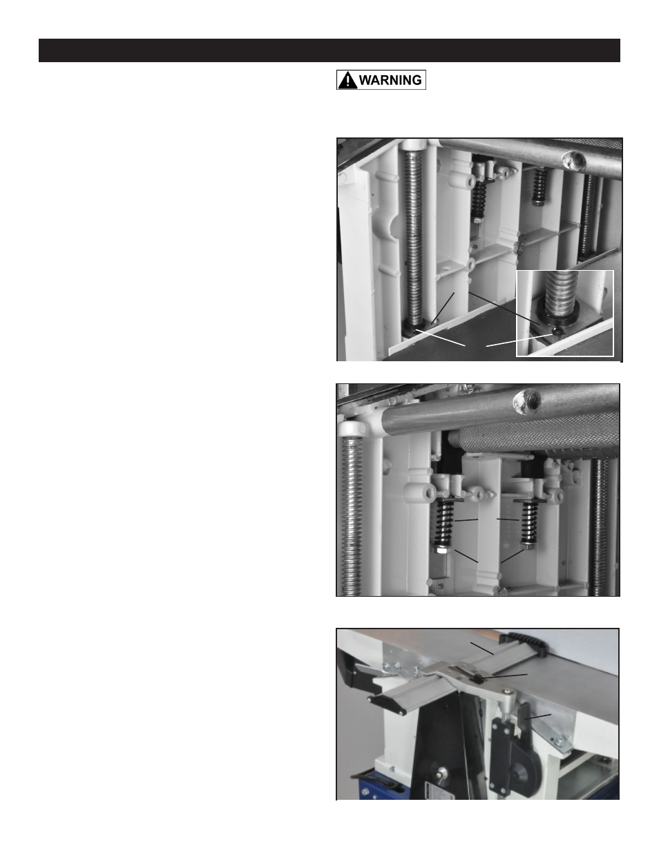
ADJUSTING THE PLANER TABLE
1. The planer table is attached to the cabinet and move
vertically by four Threaded Spindles, or posts (#131, FIG.
24, A). At the base of the spindles, there are positioning
Plates (#141, B). Next to the spindle ends, there are four
Set Screws (#140, C) that can be adjusted to slightly raise
or lower an end of the planer table so that it will be parallel
with the cutterhead.
2. Slightly loosen the four set screws at the corners of the
base plate. Depending on which side of the planer’s table
needs to be raised, turn the set screws at that side of the
base to raise the base/table.
3. Repeat measuring with the gauge block and making
adjustments until the table is parallel with the cutterhead.
4. Remove the gauge block from the mouth of the planer
and check all parts to confirm the machine is ready for use.
FIG. 24
ADJUSTING THE FEED ROLLERS
The Infeed (#138) and Outfeed (#136) Rollers are pre-set
by the factory to align parallel with the cutterhead and knife
inserts. These spring loaded rollers are set just below the
cutterhead, so that they engage the lumber and move it
through the planer. Should an adjustment be required to in-
crease or decrease the amount of downward pressure they
exert on the lumber, the following steps are needed.
1. The outfeed jointer table and the fence needs to be
removed, and the dust hood lifted up and pivoted back
onto the cutterhead to gain access inside of the planer. See
page 14, step 2 and FIG. 22 on this process.
2. Under the Feed Rollers, the long Hex Head Bolts (#147,
D) hold the compression Springs (#145, E) in place, and
control the pressure the rollers exert onto the lumber being
moved throuh the planer for surfacing. The bolts can be
tightened or loosened with a 13mm wrench. FIG. 25.
- By tightening the bolts, UP the frame, the spring is
compressed and the downward pressure of its roller is
increased upon the lumber being fed through the planer.
- By loosening the bolts, DOWN the frame, the spring
compression is reduced, and its rollers exert less pressure
down onto the lumber.
3. Once the rollers are set, the machine is ready for use.
THE MACHINE MUST NOT BE
PLUGGED IN AND THE POWER SWITCH MUST BE IN THE
OFF POSITION UNTIL ALL ADJUSTMENTS ARE COMPLETE.
FIG. 25
A
B
C
A
OUTFEED
ROLLER
D
E
ADJUSTING THE CUTTERHEAD GUARD
The Guard Bar (#207, A) must be covering the cutterhead’s
sharp knives at all time to keep you safe during jointing.
- Adjust the height of the cutterhead guard, with the
Guard Setting Lever (#226, FIG. B, B).
- Adjust and lock the Guard (B) in place over the cut-
terhead knives with the Clamping Lever (#208, C). The
guard’s forward plastic, spring end will exert slight priessure
against workpieces when used in jointing mode.
FIG. B
A
B
C