Adjustments, Fig. 19, Fig. 20 fig. 21 – RIKON Power Tools 25-010H User Manual
Page 13
13
ADJUSTMENTS
The jointer fence provides lateral support for the work-
piece when surface planing.
It can be tilted to any angle
between 90° and -45°, and moved forward or backwards
over the jointer bed and cutterhead to match the
workpiece width. Once the fence is installed (page 11), it
must be accurately set at 90º. To do this you will need an
accurate square.
SETTING THE FENCE TO 90° AND 45°
1. Loosen the upper Ratchet Handle (#265) and adjust the
fence into position against the square.
2. When the fence extrusion is exactly at 90º, tighten the
upper ratchet handle to secure the position.
3. Set the rear, lower 90º Stop Screw (#221) on the fence
Bracket (#201). This will ensure that the fence always
returns to 90º. FIG. 20.
4. This same operation should also be carried out for set-
ting the fence at the 45º angle, and fastening the upper 45°
Stop Screw. FIG. 20. Note: the 45° angle is actually 135°
from the jointer table.
SETTING THE FENCE ALONG THE TABLE LENGTH
The jointer fence can be moved forward or backward
along the length of the jointer tables, and over the
cutterhead, to allow for different board lengths.
1. On the rear of the fence, loosen the two hex Bolts
which attach the Fence Bracket to the Fence through the
long center slot in the fence rear. FIG. 21.
2. Move the fence to your desired position on the jointer.
3. Re-tighten the two hex bolts to secure the fence in its
now position.
4. Check the alignment of the tables with the straight edge
on both front and rear sides of the of the tables. Make
further adjustments with the guide screws as necessary,
until the tables are parallel with each other.
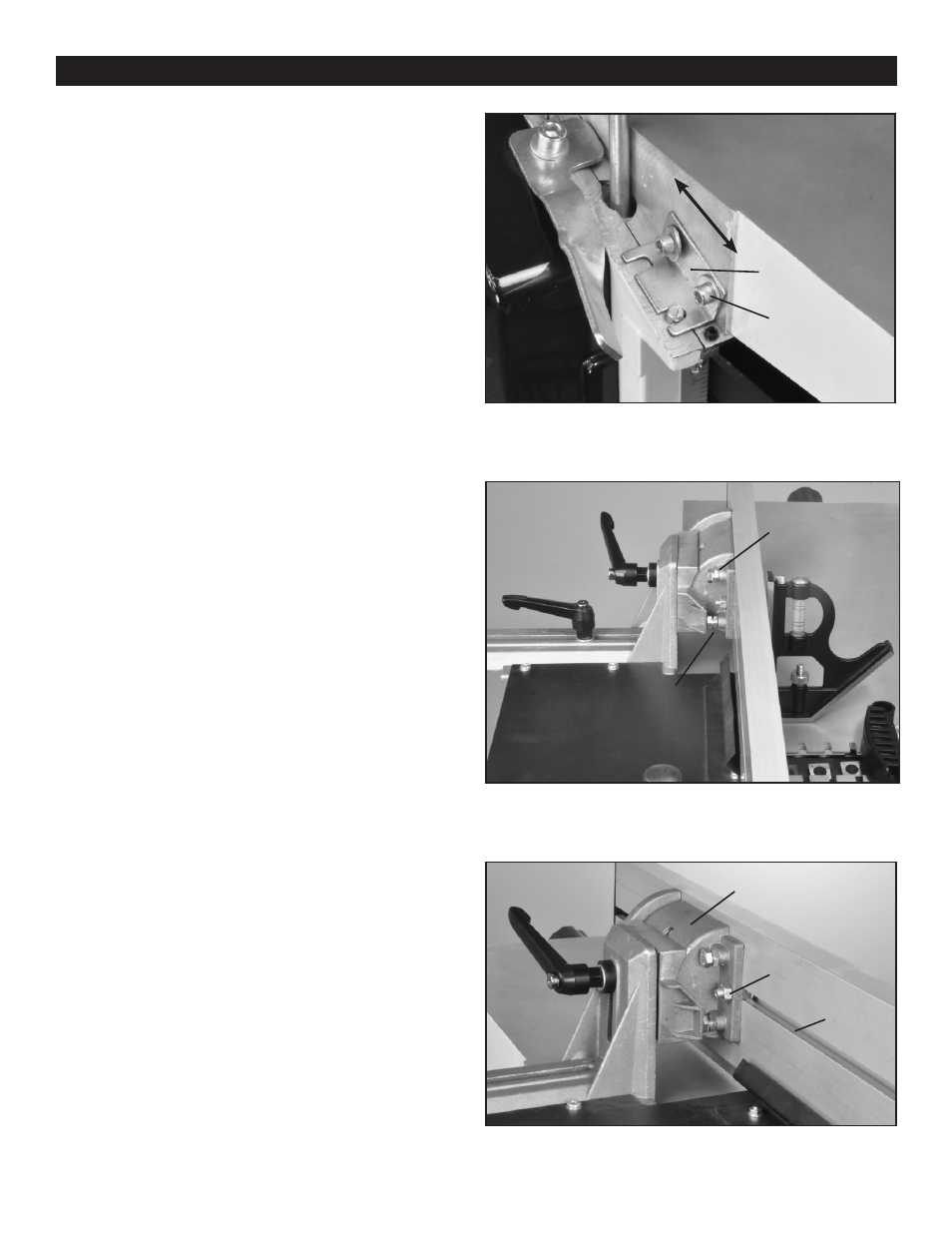
5. To adjust the HEIGHT of the table, loosen the hex Bolts
that fasten the Brackets (#158) to the side of the outfeed
table. Carefully slide the table forward or backwards to
change the table height. FIG. 19. Re-fasten the bracket’s
hex bolts once the two tables are level with each other.
NOTE: To make this adjustment, you could also measure
the height difference between tables with dividers or cali-
pers. Then remove the outfeed table and re-set the bolts in
the bracket’s elongated holes to this measured distance.
FIG. 19
JOINTER FENCE ADJUSTMENT
FIG. 20
FIG. 21
DEPTH SCALE
GUIDE SCREW
OUTFEED
TABLE
BOLT
BRACKET
RATCHET
HANDLE
90° STOP
SCREW
45° STOP
SCREW
FENCE BRACKET
HEX BOLT
SLOT IN
FENCE
BACK