Assembly, Contents of package, Fig. 2 – RIKON Power Tools 23-400H User Manual
Page 8: Fig. 1
8
ASSEMBLY
THE PLANER MUST NOT BE PLUGGED IN AND THE POWER SWITCH
MUST BE IN THE OFF POSITION UNTIL ASSEMBLY IS COMPLETE.
Unpacking and Clean-up
1. Carefully remove all contents from the shipping carton. Compare the contents with the list of contents to make sure
that all of the items are accounted for, before discarding any packing material. Place parts on a protected surface
for easy identification and assembly.
2. Report any shipping damage to your local distributor.
3. Clean all rust protected surfaces with ordinary house hold type grease or spot remover. Do not use; gasoline, paint
thinner, mineral spirits, etc. These may damage painted surfaces.
4. Apply a coat of paste wax to the table to prevent rust. Wipe all parts thoroughly with a clean dry cloth. Be careful
when reaching inside of the planer as the knives are sharp and may cause injury if touched.
5. Set packing material and shipping carton aside. Do not discard until the machine is set up and is running properly.
INSTALLING THE HAND WHEEL
The handwheel, which raises and lowers the planer's
table, must be installed.
FIG. 2.
1. Slip the hand wheel (#87) onto the crank bar shaft
(#91). Postion the wheel so that the flat section on the
shaft is aligned with the set screw that is pre-installed in
the hub of the handwheel.
2. Secure the wheel in place with the Set Screw (#86).
FIG. 2
HAND
WHEEL
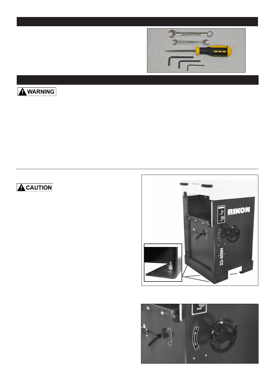
INSTALLING THE PLANER
When moving the planer, DO NOT
carry it with the infeed and outfeed rollers. Use a
forklift, or pallet jack under the machine to lift and
move the planer.
1. Position the planer on a solid, level foundation that
is located in an area that ample space in front and in
back of the planer for the moving of lumber to be milled.
Align the machine so that during use, any kickback
will not face aisles, doorways, or other work areas that
bystanders may be in. Do not locate or use the machine
in damp or wet conditions.
2. The planer is firmly bolted to a pallet with 4 bolts
and nuts. Once the planer is in the area where it will
reside, unbolt the planer from the pallet. The bolts are
located through the two openings at the bottom sides of
the planer. Carefully inch-it off the pallet by pushing the
lower body/frame of the planer. DO NOT push the upper
lid as this may damage the machine. FIG. 1.
3. Secure the machine to the floor with lag screws (not
supplied). Use the same 4 holes that secured the planer
to the pallet for transport.
CONTENTS OF PACKAGE
Tools for Assembly & Adjustments
A. Wrenches - 13mm , 10mm & 8mm
B. Star T25 Screwdriver
C. Hex Wrenches - 2.5mm, 4mm & 5mm
A
B
C
FIG. 1