Adjustments, Fig. 27, Fig. 26 – RIKON Power Tools 23-400H User Manual
Page 16
16
ADJUSTMENTS
FIG. 27
10. When all belts have been checked and any mainten-
ace has been done, replace and secure the side panel
and speed control knob back to their positions with the
screws that were previously removed (In steps 2 & 3).
REPLACING THE DRIVE BELTS
1. To replace the
Cutterhead Drive Belt (#145, FIG.
26, A), follow the same steps, #2-6 above (page 15) to
remove the side panel and access the belts and pulleys.
Loosen the tension until both the Cutterhead Drive Belt
and the Feed Roller Belt (#152, B) can be easily removed
from both their pulleys.
The small Panel (#150, c) that surrounds the speed con-
trol arbor must be removed to slide the two used belts off
of the motor arbor. Once removed, reverse the steps to
install and re-tension the new belts on their pulleys.
2. To replace the
Feed Roller Belt (#152, B), the small
Panel (C) must first be removed. With the motor loose
and lifted, there should be enough slack to install a new
Feed Roller Belt. If not, the tensioning Spring (#184, D)
can also be un-hooked to allow the Cam Wheel Bracket
(#244) to swing loose. Re-fastened the spring once the
belt has been installed. Then reverse the steps to install
the drive belt and re-tension it on the pulleys.
3. When all work on the belts has been done, replace the
small panel, cabinet side panel, and the speed control
knob and secure them in position with the same screws
that were previously removed.
Drive Belt Adjustment continued from page
15
THE PLANER MUST NOT BE
PLUGGED IN AND THE POWER SWITCH MUST BE
IN THE OFF POSITION UNTIL ADJUSTMENTS ARE
COMPLETE.
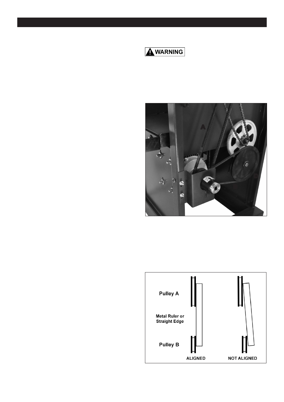
ALIGNING THE PULLEYS
The pulley positions for the belts are pre-set at the
factory for proper alignment to each other. If they are not
set correctly, excess wear to the belts and power transfer
may be reduced. While the side panel is open, the
pulleys should be checked to make sure that no move-
ment has occured during use.
1. With a metal straight edge, or perfectly flat board,
place the straight edge against the faces of the two
pulleys that are connected by the same belt. FIG. 27.
2. If the straight edge does not lie flat on both of the
pulley faces, one or both of the pulleys must be moved to
correct this miss-alignment.
3. Loosen the pulleys' set screws and shift the pulleys
along their shafts until they are properly aligned.
4. Tighten the pulley set screws and them re-check the
belt tension as described on page 15.
FIG. 26
A
B
C
D
MOTOR
MOUNT