Site preparation, Frame assembly, Assembly instructions – Rhino Shelter EXT ROUND-12WX24LX8H User Manual
Page 3
Assembly Instructions
Extended Round Style 12 x 24 x 8
V2.2
Please Do NOT Return Assembly to Dealer or Store. For All questions or Shortages please call MDM Products directly
Customer Service 800-447-7079 or 203-877-7070
3
SITE PREPARATION
Select a level or as close to level as practical location for
your Rhino Shelter unit. The unit should be placed on a
base of materials suitable for the storage load to be
protected. The unit should not be located under trees,
which will shed hard fruit such as apples, walnuts, or
heavy pine cones. The cover of your unit will protect
against normally leaves and light debris, however large
branches or other falling items may cause puncture or
tears in the cover material.
Take notice of drainage around your intended location.
Water draining from the surrounding terrain should be
planned so that it does not run into the unit. As well, rain
or melting snow that comes off the unit should be
drained away rather than accumulate and pool around
the unit.
Check to be certain that adequate clearance is allowed
for entry and exit from ends of unit. As unit has doors on
both ends, ideally vehicle or equipment can be inserted
or removed from either end.
FRAME ASSEMBLY
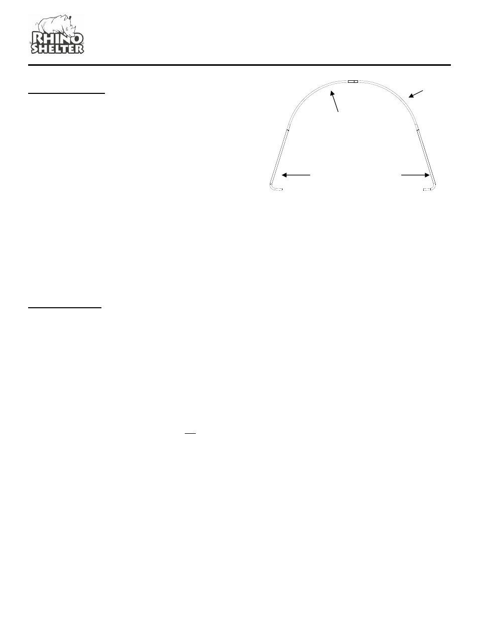
Step1. Assemble the two End Arch Assemblies. Each
consists of (1) Right Side Crest Tube RC-3020, (1) Left
Side Crest Tube LC-3021 and (2) End Upright w/Foot
EUL-4021 for each one. Assemble as shown below.
The swedged ends slip into the plain end pipe of the
adjoining frame member. Use (4) CBN-3005-3 carriage
bolts with nuts and curved washers through pre-drilled
holes in frame members.
Be certain to insert carriage bolts from the outer edge
into the interior of the unit, with the washers and nuts on
the inside of the arches. This will avoid tearing the fabric
on doors and main cover when installed. Do not tighten
the nuts completely until the frame is completed and set
in place.
Step 2. Attach the (2) Corner Wind Braces CW-1800
(flattened ends) to the End Upright w/Foot EUL-4021 to
the first of the End Arch assemblies. Use a CBN-3005-2
Carriage Bolt with Washer and Nut to secure the braces
loosely to the Upright, into the hole just below the side
cross rail. Do not tighten completely.
Step 3. Assemble the Five Interior Arch Assemblies
using (1) Right Crest Tube RC-3020, (1) Left Crest Tube
LC-3021, and (2) Center Straight Upright CSU-4020 for
each. Use CBN-3000-3 carriage bolts with washers and
nuts in the pre-drilled holes, aligned to form each arch.
Place aside for the moment.
Step 4. Support an End Arch with Wind Braces CW-
1800 temporarily in the vertical position. Connect (4)
ECR-2031 Plain End Cross Rails to the inside of the End
Arch onto the (4) CBN-3005-3 carriage bolts that
assembled the interior arch members. The Cross Rails
should be put into the bottom and side hole of each arch
upright. These will begin the Base Cross Rails and Side
Cross Rails on each side of the frame assembly. Again,
don’t tighten the hardware until the next arch and cross
rails are assembled.
Step 5. Stand an Interior Arch Assembly up vertically
approximately 48” from the End Arch Assembly with
cross rails. Align the cross rails from the End Arch with
the carriage bolt holes in the Interior Arch. Remove the
(4) nuts and washers on the carriage bolts, and connect
the cross rails between the End Arch and the first Interior
Arch. Connect the (2) Wind Braces #CW-2005
diagonally across the end and interior arch as shown in
the frame illustration.
RC-3020 Right
Crest Tube
LC-3021 Left
Side Crest Tube
EUL-4021 End Upright
With Foot