Operation – Lincoln Electric IM992 VANTAGE 300 User Manual
Page 24
B-5
OPERATION
B-5
VANTAGE® 300
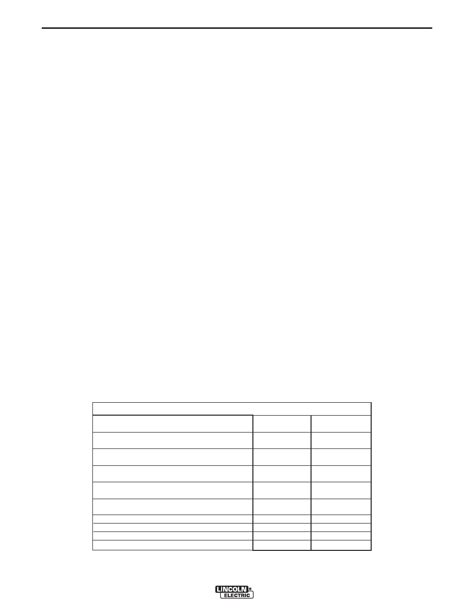
TYPICAL VANTAGE® 300 FUEL CONSUMPTION
Deutz D2008 L4
Gal./Hr (Liters/Hr)
---------
.34 (1.30)
---------
.46 (1.75)
-----------
.64 (2.41)
-----------
.86 (3.24)
-------------
1.22 (4.62)
1.10 (4.15)
.89 (3.36)
.73 (2.75)
.58 (2.18)
Running Time for
20 gallons - (Hours)
--------
58.41
--------
43.28
--------
31.39
--------
23.36
--------
16.37
18.23
22.51
27.53
35.41
1400 R.P.M.
1800 R.P.M.
DC Weld Output 150 Amps @ 20 Volts
DC Weld Output 250 Amps @ 24 Volts
DC Weld Output 300 Amps @ 32 Volts
10,000 Watts
7,500 Watts
5,000 Watts
2,500 Watts
NOTE: This data is for reference only. Fuel consumption is approximate and can be influenced
by many factors, including engine maintenance, environmental conditions and fuel quality.
Low Idle - No Load
High Idle - No Load
STOPPING THE ENGINE
Remove all welding and auxiliary power loads and
allow the engine to run at low idle speed for a few
minutes to cool the engine.
STOP the engine by placing the RUN-STOP switch in
the STOP position.
NOTE: A fuel shut off valve is located on the fuel pre-
filter.
WELDER OPERATION
DUTY CYCLE
Duty Cycle is the percentage of time the load is being
applied in a 10 minute period. For example a 60% duty
cycle, represents 6 minutes of load and 4 minutes of no
load in a 10 minute period.
ELECTRODE INFORMATION
For any electrode the procedures should be kept with-
in the rating of the machine. For information on elec-
trodes and their proper application see (www.lincoln-
electric.com) or the appropriate Lincoln publication.
The VANTAGE® 300 can be used with a broad range of
DC stick electrodes. The MODE switch provides two
stick welding settings as follows:
CONSTANT CURRENT (CC-STICK) WELDING
The CC-STICK position of the MODE switch is designed
for horizontal and vertical-up welding with all types of
electrodes, especially low hydrogen. The OUTPUT CON-
TROL dial adjusts the full output range for stick welding.
The ARC CONTROL dial sets the short circuit current
(arc-force) during stick welding to adjust for a soft or
crisp arc. Increasing the number from -10(soft) to
+10(crisp) increases the short circuit current and pre-
vents sticking of the electrode to the plate while welding.
This can also increase spatter. It is recommended that
the ARC CONTROL be set to the minimum number with-
out electrode sticking. Start with the dial set at 0.
NOTE: Due to the low OCV with the VRD on, a very
slight delay during striking of the electrodes may
occur. Due to the requirement of the resistance in the
circuit to be low for a VRD to operate, a good metal-
to-metal contact must be made between the metal
core of the electrode and the job.
A poor connection anywhere in the welding output cir-
cuit may limit the operation of the VRD. This includes
a good connection of the work clamp to the job. The
work clamp should be connected as close as practical
to where the welding will be performed.
A. For New Electrodes
E6010 - Touch, Lift to Start the Arc
E7018, E7024 - Touch, Rock Back and Forth in Joint,
Lift .
Once the arc is started, normal welding technique for
the application is then used.
B. For Re-Striking Electrodes
Some electrodes form a cone at the end of the elec-
trode after the welding arc has been broken, particu-
larly iron powder and low hydrogen electrodes. This
cone will need to be broken off in order to have the
metal core of the electrode make contact.
E6010 - Push, Twist in Joint, Lift
E7018, E7024 - Push, Rock Back and Forth in Joint,
Lift.
TABLE B.2