Operation, B-22 – Lincoln Electric IM956 POWER WAVE C300 User Manual
Page 43
B-22
OPERATION
B-22
POWER WAVE
®
C300
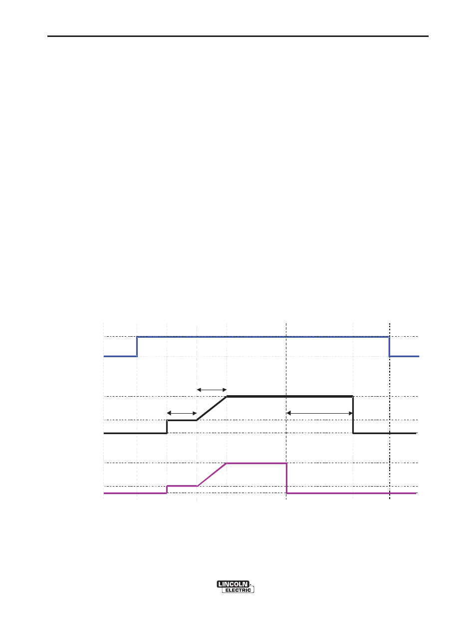
EXAMPLE 2 - 2 STEP TRIGGER: Improved Arc Start
and Arc End. Tailoring the arc start and arc end is a
common method for reducing spatter and improving
weld quality. This can be accomplished with the Start
and Burnback functions set to a desired values and
Crater set to OFF. (See Figure B.12)
For this sequence,
PREFLOW:
Shielding gas begins to flow immediately when the
gun trigger is pulled.
RUN-IN:
After preflow time expires, the power source regulates
to the start output and wire is advanced towards the
work piece at the Run-In WFS. If an arc is not estab-
lished within 1.5 seconds, the power source output
and wire feed speed skips to the weld settings.
UPSLOPE:
Once the wire touches the work and an arc is estab-
lished, both the machine output and the wire feed
speed ramp to the weld settings throughout the start
time. The time period of ramping from the start set-
tings to the weld settings is called UPSLOPE.
WELD:
After upslope, the power source output and the wire
feed speed continue at the weld settings.
BURNBACK:
As soon as the trigger is released, the wire feed
speed is turned OFF and the machine output contin-
ues for the burnback time.
POSTFLOW:
Next, the machine output is turned OFF and shielding
gas continues until the post flow timer expires.
Shielding
Gas
Idle
Preflow
Run-In
Upslope
Weld
Burnback
Postflow
Idle
WFS
On
Off
Run-in
Off
Weld
Off
Weld
Arc
Established
T
rigger
Pulled
T
rigger
Released
2 Step Trigger
Start = ON
Crater = OFF
Burnback = ON
1.5 sec max.
Start
Start tim e
Burnback Time
Power
Source
Output
FIGURE B.12