Installation – Lincoln Electric IM584 Power Feed 10 Wire Drive & Control Box User Manual
Page 17
A-9
INSTALLATION
POWER FEED 10
A-9
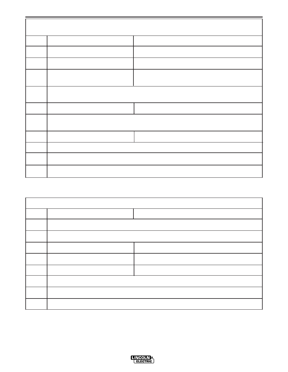
S1 DIP Switch Bank on Control Box Motherboard (For software version S24456)
Switch
Off
On
1
Standard speed gearbox limits adjustable
High speed gearbox limits adjustable
2
WFS Display = inches/minute
WFS Display = meters/minute
3
Left Display is always preset WFS
Left Display is preset WFS when weld current is not flowing
Left Display is actual weld current when weld current is flowing
CC modes override this switch regardless of position. Left Display is always preset weld cur-
rent when weld current is not flowing and actual weld current when weld current is flowing
4
Run-in = Minimum Speed Available
Run-in = weld WFS
If any option containing a Run-in setting is connected to the motherboard, it automatically
overrides this switch regardless of position.
5
Memory change with trigger disabled
Memory change with trigger enabled
6
Acceleration, MSB (Sets acceleration rate for wire drive) see below
7
Acceleration (Sets acceleration rate for wire drive) see below
8
Acceleration, LSB (Sets acceleration rate for wire drive) see below
MSB - Most Significant Bit or Byte. This is the bit in a binary number or DIP switch bank that is furthest to the left.
LSB - Least Significant Bit or Byte. This is the bit in a binary number or DIP switch bank that is furthest to the right.
S2 DIP Switch Bank on Control Box Motherboard (For software version S24456)
Switch
Off
On
1
Network Group ID, MSB (Assigns Control Box to a specific group) (Off is factory setting)
2
Network Group ID, LSB (Assigns Control Box to a specific group ) (Off is factory setting)
3
4-Step Domestic Configuration
4-Step European Configuration
4
Power Feed 10 / Dual
Power Feed 11
5
Procedure Change with Trigger “OFF”
Procedure Change with Trigger “ON”
6
Set lower limits
7
Set upper limits
8
Must be on for all units (Permits selection of extended modes)
Note: the factory shipped settings for the S2 switches are as follows:
PF-10 (and Dual) Domestic - switches 1-7 “OFF”, 8 “ON”
PF-10 (and Dual) European - switches 1,2,4-7 “OFF”, 3,8 “ON”
PF-11 Domestic - switches 1-3,5-7 “OFF”, 4,8 “ON”
PF-11 European - switches 1,2,5-7 “OFF”, 3,4,8 “ON”
Note: the factory shipped settings for the S1 switches are as follows:
PF-10 (and Dual) Domestic - All switches “OFF”
PF-10 (and Dual) European - switches 1 & 3-8 “OFF”, 2 “ON”
PF-11 Domestic - switches 2-8 “OFF”, 1 “ON”
PF-11 European - switches 3-8 “OFF”, 1,2 “ON”