Operation, Welder/generator controls, Controls and settings – Lincoln Electric IM973 OUTBACK 145 User Manual
Page 18
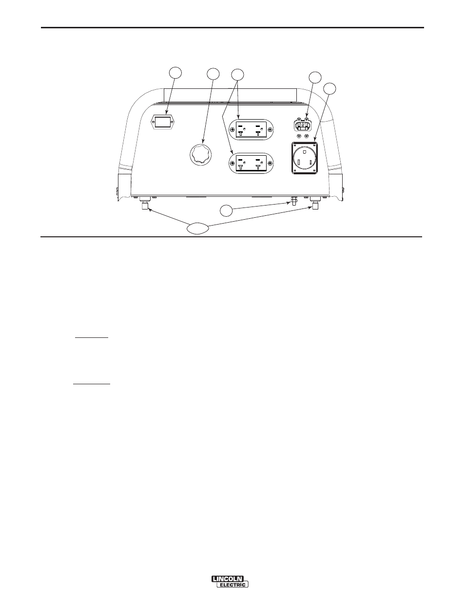
1
2
7
8
3 or 4
6
5
B-4
OPERATION
B-4
OUTBACK™ 145
®
CONTROLS AND SETTINGS
All welder/generator controls are located on the Output Control Panel.
Gasoline engine controls are mounted on the engine. See Figure B.1 and the figures in engine operation section.
WELDER/GENERATOR CONTROLS
See Figure B.1 for the location of the following features:
1. CURRENT CONTROL DIAL:
Adjusts continuous cur-
rent output. The amperages on the dial correspond to
the approximate amperages needed for specific
Lincoln welding electrodes.
2. 20 AMP CIRCUIT BREAKER:
Provides overload cur-
rent protection for the 120 Volt and 240 Volt
Receptacles
3. WELD POSITIVE OUTPUT TERMINAL:
Pro vides the
connection point for either the electrode holder or the
work cable. (Because the OUTBACK™ 145 is a DC
output machine, either output terminal can be used for
either cable.)
4. WELD
NEGATIVE OUTPUT TERMINAL: Provides the
connection point for either the electrode holder or the
work cable. (Because the OUTBACK™145 is a DC
output machine, either output terminal can be used for
either cable.)
5. GROUND STUD:
Provides a connection point for con-
necting the machine case to earth ground for the
safest grounding procedure.
OUTPUT PANEL CONTROLS
FIGURE B.1
6. 240 VOLT RECEPTACLE:
Connection point for sup-
plying 250 volt power to operate one electrical device.
7. 120 VOLT DUPLEX RECEPTACLES (2):
Connection
point for supplying 120 volt power to operate one or
has run for maintenance purposes.
8. HOUR METER:
Records the time that the engine has
run for maintenance purposes.