Installation, Fig. 13, Fig. 12 – Lincoln Electric IM621 Mobiflex 200-M K1653-1,-2 User Manual
Page 14
A-7
INSTALLATION
MObIFLEX 200-M
A-7
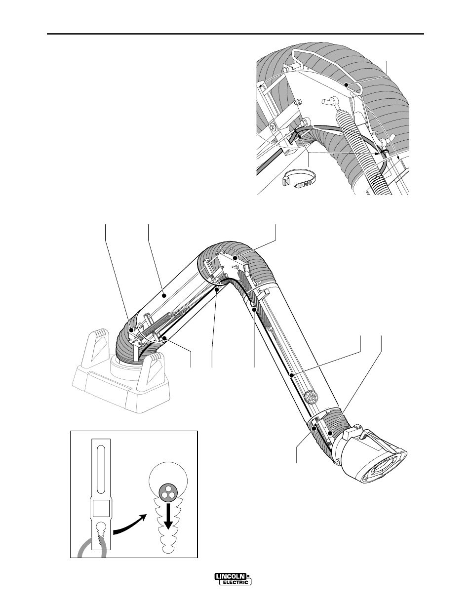
INSTALLING THE OPTIONAL
LAMP KIT AND AUTOMATIC
START/STOP ARC SENSOR
(continued)
Route the 13 ft. connecting cable through the four
cable holders in the arm (Fig. 12, Points D). Leave
plenty of slack at each hinge to allow for the full range
of movement of the arm. Secure the cable in the
cable holders (Fig. 12, Inset). Exit the arm through the
cable hole in the rotating hinge; use a knife to cut a
small X-pattern in the grommet and push the cable
through.
Use the supplied wire ties to secure the cable as
shown in Fig. 13.
Seal all hose joint connections with the rubber seals.
L=min. 22"
(550 mm)
Client: Lincoln/Euromate
Client no/project no: 123380/170241-12
Date: 04.12.1997
Drawing no/archive no:lusKK102.eps
Version no: 1
Illustrator: Jos Taabe
Description:
kabeldoorvoer frictiescharnier.
L=min. 22"
(550 mm)
Client: Lincoln/Euromate
Client no/project no: 123380/170241-12
Date: 04.12.1997
Drawing no/archive no:lusKK102.eps
Version no: 1
Illustrator: Jos Taabe
Description:
kabeldoorvoer frictiescharnier.
Fig. 13
D
D
4x
A
B
A
C
A
D
D
Client: Lincoln/Euromate
Client no/project no: 123380/170241-12
Date: 04.12.1997
Drawing no/archive no:lusKK101.eps
Version no: 1
Illustrator: Jos Taabe
Description:
kabeldoorvoer algemeen.
D
D
4x
A
B
A
C
A
D
D
Client: Lincoln/Euromate
Client no/project no: 123380/170241-12
Date: 04.12.1997
Drawing no/archive no:lusKK101.eps
Version no: 1
Illustrator: Jos Taabe
Description:
kabeldoorvoer algemeen.
Fig. 12