Magnum 250 lx - installation, Spool gun familiarization – Lincoln Electric IM887 K2490-1 MAGNUM 250 LX SPOOL GUN User Manual
Page 10
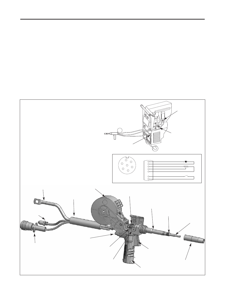
Spool Gun Familiarization
Become familiar with your spool gun before connecting to welder.
For features described below, refer to Figure on the next page.
1. Handle, gun can be used in either right or left hand.
2. Trigger operates welding power, gas flow, and wire feed.
3. Remote wire speed control, located behind the handle, controls
the speed of the drive motor.
4. Open body cover by flipping lid and observe the following:
a. Wire drive release lever up position moves pressure roller
away from drive roll to stop wire feed. Down position moves
pressure roller to wire. Operate wire drive release lever and
see pressure roller move.
b Drive roll with two wire grooves. Narrow groove feeds .030 or
.035 (0.9 mm) diameter wire. Wide groove feeds 3/64 inch (1.2
mm) diameter wire. Gun is shipped with wide groove or 3/64
in operating position (toward handle). Reverse roller for .030
or .035 inch (0.9 mm) diameter wire.
5. Gas nozzle directs gas flow around arc. Pull off gas nozzle to see
contact tip and gas diffuser. Spool gun is shipped with 3/64th inch
(1.2 mm) contact tip installed.
6. Electrode wire spool cover. Remove by unscrewing knob.
Electrode wire goes into gun through rear plastic tube.
7. Cable assembly for power, control, and gas.
Reassemble gun with spool of wire in spool holder. Hold gun and
become familiar with gun's weight and balance.
MAGNUM 250 LX - INSTALLATION
4
CONTACT TIP
ELECTRODE WIRE
SPOOL COVER
PRESSURE
ROLLER
GAS NOZZLE
TRIGGER
DRIVE ROLL
RELEASE
LEVER
HANDLE
7 PIN CONTROL
PLUG FOR
TRIGGER, WIRE
SPEED MOTOR
WIRE SPEED
CONTROL
POWER CABLE
GAS HOSE
GAS
DIFFUSER
CABLE
ASSEMBLY
DRIVE
ROLL
NECK
+ POSITIVE
CABLE AND STUD
GAS HOSE AND
5/8 FITTING
7-PIN SPOOL GUN
RECEPTACLE
CONNECTING TO POWER SOURCE:
1. Power source must be “off” and power cord
disconnected.
2. Connect power cable to positive “+” stud.
Connect work cable & clamp to “-” stud.
3. Connect 7-Pin control cable plug to power
source receptacle.
4. Connect spool gun GAS hose to Gas solenoid
fitting.
5. Reconnect power and turn on machine.
A
B
C
D
E
G
F
"W" CLOCKED
CONNECTOR
(VIEWED FROM FRONT OF CONNECTOR)
A
B
G
D
F
E
TORCH
FUNCTIONS
+
-
MOTOR
TORCH
C
POT
TORCH
1
3
2
5K
CW
TORCH
TRIGGER
RED
BLACK
WHITE
GREEN
BLUE
BROWN
YELLOW/ORANGE