Installation, Mounting the ln-10 control box, Connecting wire drive unit to control box – Lincoln Electric IM587 LN-10 Wire Feeder User Manual
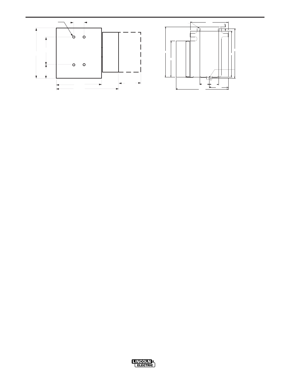
Page 11: Figure a.2
A-3
INSTALLATION
LN-10
A-3
FIGURE A.1
Mounting Synergic 7F Wire Drive Unit
(K679-1 or -2)
Mount the wire feed unit by means of the insulated
mounting bracket attached to the bottom of the gearbox.
Reference L9777 (included with Drive unit) to find the
size and location of the mounting holes. The gearbox
assembly is electrically “hot” when the gun trigger is
pressed. Therefore, make certain the gearbox does not
come in contact with the structure on which the unit is
mounted.
The wire feed unit should be mounted so that the drive
rolls are in a vertical plane so dirt will not collect in the
drive roll area. Position the mechanism so it will point
down at about a 45° angle so the wire feed gun cable will
not be bent sharply as it comes from the unit.
Note: The K1562-1 control box must be used with the
K679-1 or -2.
Mounting the LN-10 Control Box
The same control box is used for both a 10 Series drive,
or a Synergic 7F drive. The back plate of the control box
has two keyhole slots and one bottom slot for mounting.
See Figure A.2 for the size and location of these slots.
Mount the box at some convenient location close to the
wire drive unit which will enable the desired control cable
to reach between the control box and the wire drive unit.
a) Drill the required holes in the mounting surface,
partially install 1/4-20 screws.
b) Mount the box.
c) Tighten the screws.
Connecting Wire Drive Unit to Control Box
One head to control cable assembly is required. The
Head to Control cable assemblies are available in two
types:
K1498-"L" -Includes a control cable with 14-pin ms-style
connectors on each end, and a 3/0 weld
cable (rated 600 amps, 60% duty cycle) to
route between the wire drive and the control
box. Available in lengths "" of 16 ft. (4.9 m),
20 ft. (6.1 m) and 25 ft. (7.6 m)
K681-"L" - Same as K1498, but does not include weld
cable. Available in lengths "L" of 12 ft (3.6 m),
16 ft (4.9 m) and 25 ft. (7.6 m).
a) Making certain the cables are protected from any
sharp corners which may damage their jackets,
mount the cable assembly along the boom so the end
with the female amphenol connector pins is at the
wire feed unit.
b) Connect the 14-socket cable connectors to the mating
receptacles on the back of the wire feed unit connec-
tion box.
c) At the same end, connect the electrode lead to the
1/2" connection bolt on the front of the left wire drive
head feed plate.
d) At the control box end, connect the 14 pin connectors
of the cable to the mating receptacle on the bottom of
the control box.
e) At the control box current sensor, slip the cover box
up off the sensor and connect the electrode cable(s)
to the top bolt connection.
5/16-18 THREAD
2.25
FEED PLATE
DOOR OPEN
5.00
10.50
14.50
3.00
6.00
11.00
BOTTOM FRONT
CLEARANCE
FOR 1/4 BOLT
2.63
12.75
14.50
13.75
5.25
CLEARANCE
FOR 1/4 BOLT
10.50
.50
10.00
2.63
14.00
FIGURE A.2