Installation, Output connections, Electrode and work cables – Lincoln Electric IM570 IDEALARC CV-655 User Manual
Page 14
A-5
INSTALLATION
CV-655
A-5
OUTPUT CONNECTIONS
ELECTRODE AND WORK CABLES
Use the shortest possible cable lengths. See Table
A.1 for recommended cable sizes based on length.
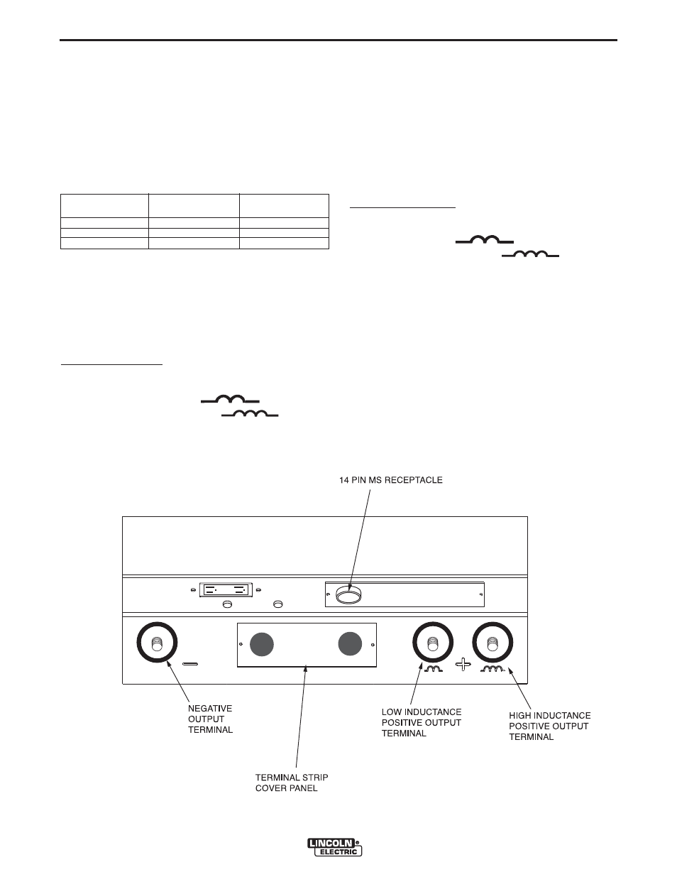
The output terminals are located at the lower front of
the welder behind a hinged door Refer to figure A.3.
Route the welding cables through the slotted strain
reliefs of the base to the welding terminals.
For Positive Polarity:
1. Connect the electrode cable to either the low induc-
tance terminal (marked " ") or the high
inductance terminal (marked " "). See
OPERATION section “Positive Output Terminals”
for an explanation of the use of high or low induc-
tance terminals.
2. Connect the work cable to the negative terminal
marked “-”.
3. Remove the terminal strip access cover panel on
the lower case front. Refer to figure A.3 for the
location.
4. Work Sense lead #21 from the 14 Pin MS-recepta-
cle must be connected to “-21”on the terminal strip.
Note: This is how the CV-655 is shipped from
the factory.
5. Replace the terminal strip access cover panel.
For Negative Polarity:
1. Connect the work cable to either the low inductance
terminal (marked " ") or the high induc-
tance terminal (marked " "). See
OPERATION section “Positive Output Terminals”
for an explanation of the use of high or low induc-
tance terminals.
2. Connect the electrode cable to the negative termi-
nal marked “-”.
3. Remove the terminal strip access cover panel on
the lower case front. Refer to figure A.3 for the
location.
4. Work Sense lead #21 from the 14 Pin MS-recepta-
cle must be connected to “+21”on the terminal strip.
5. Replace the terminal strip access cover panel.
TABLE A.1
Cable Sizes for Combined Lengths of Copper
Electrode and Work Cable
Cable Length
ft. (m)
Parallel Cables
Cable Size
0 (0) to 100 (30.4)
100 (30.4) to 200 (60.8)
200 (60.8) to 250 (76.2)
2
2
2
2/0 ( 70mm
2
)
3/0 ( 95mm
2
)
4/0 (120mm
2
)
FIGURE A.3 Output Connections