Operation, Controls and settings, Warning – Lincoln Electric IM936 PRECISION TIG 375 User Manual
Page 18
B-3
OPERATION
B-3
1. POWER SWITCH - Input line switch turns input
power ON or OFF, as indicated by the on or off sta-
tus of the front panel displays.
2. POLARITY SWITCH – The 3-position rotary power
switch has detente positions for DC-, AC and DC+
selections for the Electrode output welding polarity.
3. MODE SWITCH – The mode switch allows vertical-
ly positioned selection of the two machine welding
modes. The selected mode is indicated by a lit col-
ored panel light which permits viewing the machine
setting from a distance:
3.a STICK mode (Top position) –Red panel light
ELECTRIC SHOCK can kill.
• When the Power Source is ON in
STICK mode the Electrode circuits of
both the Stick and TIG torch cables
are electrically HOT to Work.
------------------------------------------------------------------------
• The CC Stick mode may be used for general pur-
pose stick welding (SMAW ) within the capacity of
the machine. The capacity is too limited for arc air
carbon (AAC) gouging.
• In this mode; the output terminals are activated
electrically HOT, gas flow is not activated and HOT
START and ARC FORCE levels are fixed, or
Advanced Panel selectable (See Section B-7 ), with
no front panel adjustment.
3.b TIG mode (Bottom position) – No panel light.
• When the Polarity Switch is set to AC, the TIG
mode provides continuous high frequency to stabi-
lize the arc for AC TIG welding.
Hi-Freq. turns on after preflow time with the arc
start switch closure, and turns off when the arc
goes out* after the arc start switch opens.
* Arc voltage and current are sensed to determine if
the arc is established or out.
PRECISION TIG
®
375
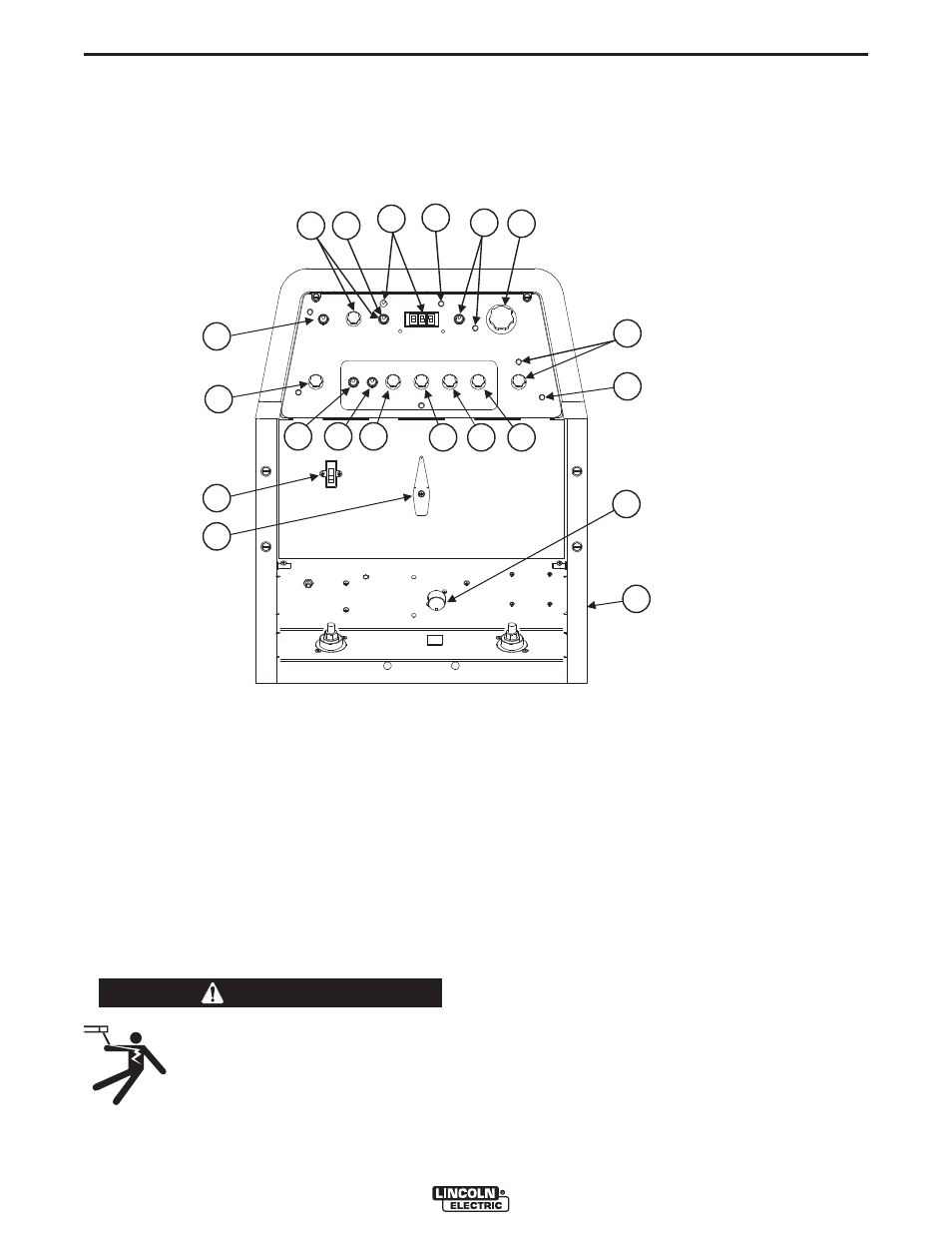
CONTROLS AND SETTINGS
The Front Control Panel contains the knobs and switches necessary for adjusting the operation of the Precision
TIG
®
375, with function indicator lights and an electronic display for volts and amps. The components are
described below:
FIGURE B.1 - CONTROL PANEL
WARNING
1
2
3
4
5
9
6
13
11
10
7
7a
14
15
16
17
(Shown without hinged stud cover.)
12
WORK
STICK
8
9
19
1. POWER SWITCH
2. POLARITY SWITCH
3. MODE SWITCH
4. AC BALANCE CONTROL
5. LOCAL/REMOTE CURRENT CONTROL
SWITCH
6. MAXIMUM OUTPUT CONTROL
7. MINIMUM OUTPUT CONTROL AND
DISPLAY SWITCH
7a
.
MENU BUTTON AND DISPLAY
SWITCH
8. DIGITAL METER AND DISPLAY
SWITCH
9. POSTFLOW TIME
10. THERMAL SHUTDOWN LIGHT
11. REMOTE RECEPTACLE
12. TRIGGER SWITCH
13. PULSE / SPOT MODE SWITCH
14. PULSE FREQUENCY CONTROL
15. PULSE % ON TIME CONTROL
16.
PULSE BACKGROUND CURRENT
CONTROL
17. DOWNSLOPE TIME
18. INTERNAL SETUP SELECTIONS (not
shown)
19. HIGH FREQUENCY INTENSITY
CONTROL (NOT SHOWN LOCATION
ONLY)