Earthway Outlet C22HDS User Manual
Page 4
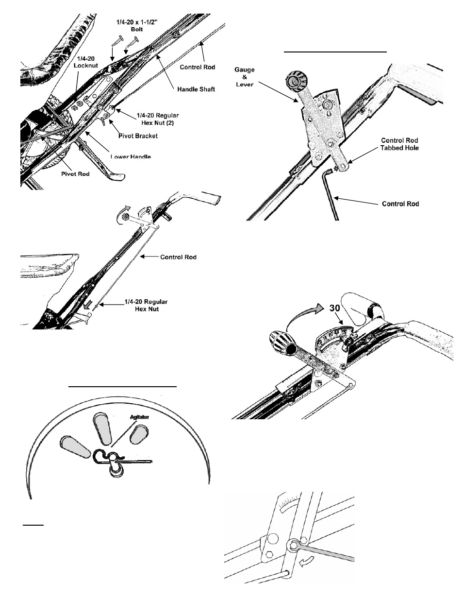
12.
Next push lever forward to setting “0”. Align control rod
with hole in pivot bracket, pull lever backward to insert control
rod through hole in pivot bracket. [T
IP
: If the lever does not
move easily, loosen slightly to make this step easier]
Now install 1/4-20 regular nut on to Control rod.
DO NOT TIGHTEN NUTS YET.
11.
I
nstall flattened end of control rod in to lever on gauge into Control
Rod Tabbed hole as shown. Turn to lock in place.
N
EXT
:
Install (1) 1/4-20 Regular Nut [not a locknut] on to Control Rod and
thread halfway as shown to the left.
13.
Pull lever back to setting “30” as shown. Next push pivot &
bracket forward so that the shut off plate in the hopper is in the full open
position. [N
OTE
: T
HE
S
ETTING
OF
“30”
ON
THE
G
AUGE
& L
EVER
A
S-
SEMBLY
MUST
OPEN
THE
S
HUT
-
OFF
COMPLETELY
FOR
PROPER
CALIBRA-
TION
.] Now tighten the nuts against the pivot bracket to prevent change
in calibration. Test by opening and closing the Gauge & Lever a few
times to ensure an accurate calibration.
14
. Insert Agitator to pinion shaft on inside of hopper.
N
OTE
: Position of flat side of agitator. This pin should be
installed as shown.
PAGE 4
15.
Tension on the flow control lever may be adjusted by
tightening or loosening the tension nut as shown on the right.
10.
Install handle shaft to lower handles and pivot & bracket assembly
as shown. Using (4) 1 ½” bolts and (4) locknuts. [T
IP
: Attach right
side first, then attach left (Pivot Bracket) side]
T
IGHTEN
BOLTS
AND
NUTS
NOW
.