Davey RAINBANK WITH SUBMERSIBLE PUMP User Manual
Page 17
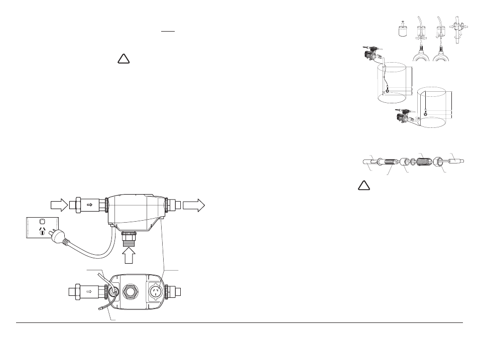
MAINS
WATER
SUPPLY
RAINWATER
SUPPLY
TO TOILETS
AND LAUNDRY
Power to pump via
3 pin socket
5 volt conne ction
for float switch
Incoming power to RainBank®
via 3 pin plug
20
17
• It is highly recommended that an
isolation valve be fitted to where the
mains water enters rainbank
®
and
between the pump and the rainwater
tank. this facilitates easy removal
of the unit if required without turning
off the household water or losing
stored rainwater.
• Do not use thread sealing compounds,
hemp or pipe glue. Do not use
crimped fittings.
• all rainbank plumbing fittings feature
rotating unions that require bracing.
• If your access to the bottom of the
rainbank
®
unit is difficult you may
have to connect the 5 volt connection
from the float switch before the
plumbing is connected.
connect all leads.
STEP 7
1. connect the pump power lead to
the three-pin socket underneath
rainbank
®
.
IMPORTANT
this must connect to the rainbank
®
controller not the power point. If the
pump is connected to the power point
the pump will run constantly,
shortening the life of the pump and
potentially running the pump dry.
2. connect the three-pin power plug from
the rainbank
®
to your power point.
3. connect the 5 volt lead from the float
switch to its flying lead; in the
underside of the unit. this is
not necessary if you are using a
submersible pump as the float switch
is already part of the pump.
!
For greater distances between your
rainwater tank and pump, a 10m float
switch (top and side entry) extension
lead (Davey part no. 14186) will need to
be added. up to 4 float switch extension
leads can be added between the pump
and the rainwater float switch lead. It
is recommended that the float switch
extension lead/s are in a protective cinduit.
STEP 3a - TOP ENTRY FlOAT SWITCH
NOTE: THE VERTICAl POSITION OF
THE FlOAT SWITCH IN RElATION TO
THE PUMP WATER INlET IS CRITCAl
1. Measure the distance from the top of
the tank (a) to the highest point of the
tank outlet to the pump (b).
2. Mark on the float switch cable a length
equal to a-b minus 200 millimeters or
distance (b) to (D).
3. Drill a hole in the top of the tank large
enough to suit a cable grommet or
strain relief grommet (F) - not supplied.
4. snap off retainer clip (c) from top of
weight (D).
5. position retainer clip 100mm from
float ball (e).
6. slide weight (e) over retaining clip and
firmly snap into position.
7. lower weight into tank and feed top of
cable through hole drilled in step 3.
8. Fasten with cable grommet to
previously measured length (a) to (b).
STEP 3b - AlTERNATE SIDE ENTRY
FlOAT SWITCH 32398
IMPORTANT
• the level switch is suitable for
installation in polyethylene and
fibreglass tanks. It can be fitted in
steel tanks but cutting through the
zinc alum or colourbond coating of
the tank exposes bare steel and this
can rust. check with the tank
manufacturer before drilling.
• the float switch is designed to be
installed from the outside of the tank.
there is no need to get inside the tank.
• the sealing grommet of the float
switch is designed to work in a
100
100
100
100
C
D
E
F
A
D
E
B
A
D
E
B
100
100
100
100
C
D
E
F
A
D
E
B
A
D
E
B
100
100
100
100
C
D
E
F
A
D
E
B
A
D
E
B
Top
Bottom
Sealing grommet
Level switch stem
Bayonnet join
Sealing nut
Compression nut
!