Part list step 8, Step 9 step 10 – Burcam F80210 ELECTRONIC HOUSE FANAIR User Manual
Page 10
10
INSTALLATION GUIDE FOR THE BURCAM’S Fan Air
MODEL F80210
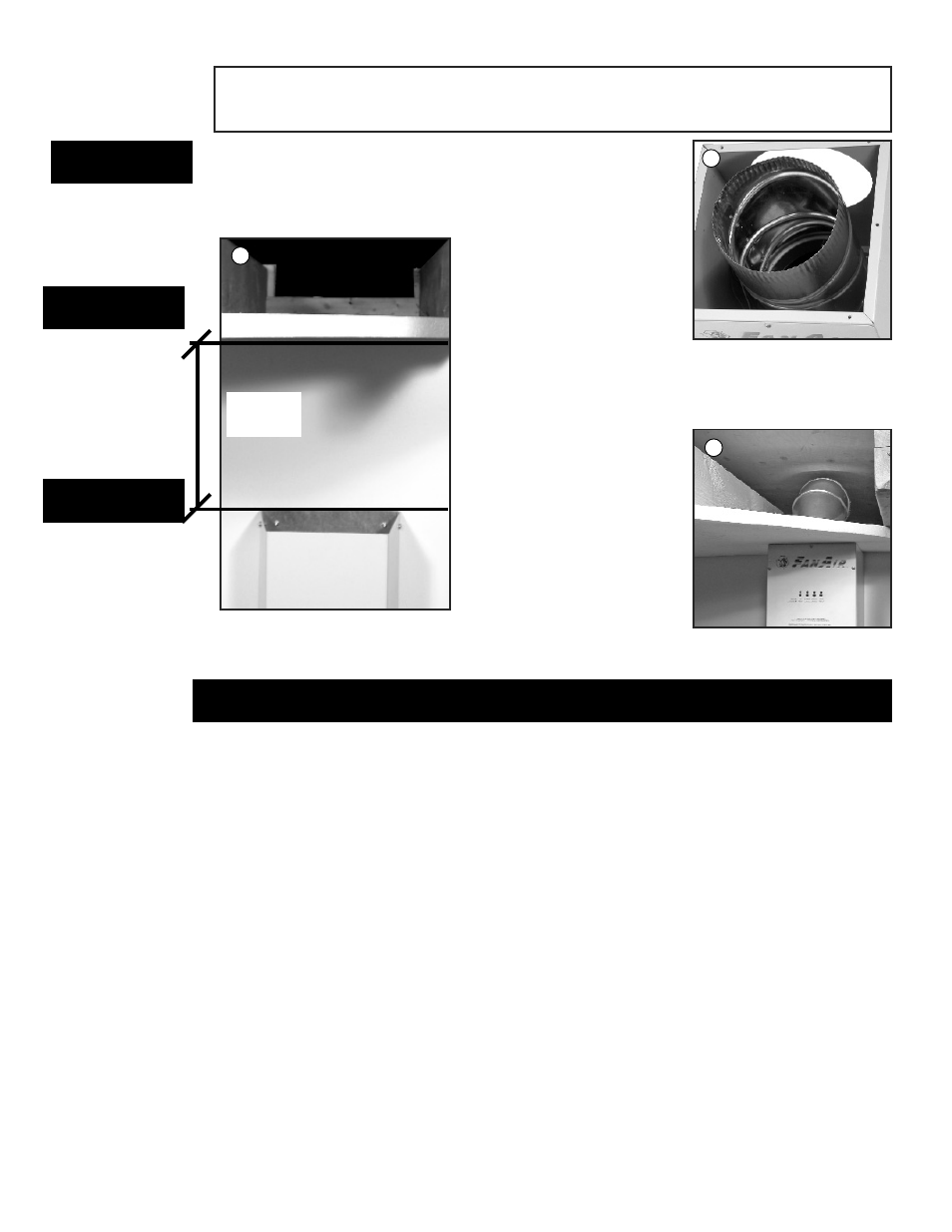
Using the screws, re-install the base of the fan to
the fan casing. The elbow is now a straight position
pushing the air to the top.
In this configuration,
the distance between
the ceiling and the
suction support is 11 1/4” (286mm).
The last step is to fix
the elbow (not included)
pre-installed in the
ceilling.
PARTS DESCRIPTION
F00250 Suction tunnel ( 3 pieces).
F00253 Suction tunnel support (2 pieces).
F00450 Fan casing (3 pieces).
F00400 Panel control.
F00401 Circuit board support (4).
F10100
Circuit board.
F10000
Relative humidity sensor kit.
F00451
Electric cord strain relief.
F00452 Electric cord.
F00351 Fan collar.
F00352 Fan and motor
F00355 Evacuation elbow.
F00254 Evacuation pipe.
F00255 Louver vent hood.
PART LIST
STEP 8
11 1/4”
286mm
9
8
10
STEP 9
STEP 10