Burcam 310100 CONDENSATE WATER PUMP User Manual
Page 5
5
M A I N T E N A N C E
7
8
16
9
13
5
6
4
2
3
1
19
15
17
14
12
10
11
18
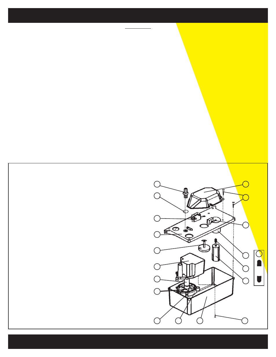
1
310386 Lower housing
2
310387 Bottom O-ring
3
310388 Pump casing
4
310389 Impeller
5
310390 Magnet rotor assembly
6
310391 Motor protector
7
310392 Outlet Adapter
8
350257 Outlet O-ring
9
310393 Casing cover
10 310394 Float casing
11 310395 Float
12 310396 Level control head
13 310397 Sensor
14 310398 Micro-switch (ON)
15 310399 Caps of shaft (2)
16 310400 Micro-switch (OFF)
17 310401 Housing screws (6)
18 310402 pump base screws (5)
19 310403 Junction cover
WARNING
Before attempting any maintenance on the unit, disconnect the power cord from the power supply
to reduce the risk of electric shock. Also, take whatever precautions are necessary if the safety
overflow switch are wired to a thermostat or alarm circuit.
IMPELLER:
- Remove the entire pump from the mounting wall.
- Disassemble the tank from the deck by removing the fours screws in the corners of the deck.
- Turn the unit upside down and remove the impeller cover by loosening the five screws on the underside
of the motor.
- The impeller and shaft assembly may then be removed and cleaned. The impeller chamber should be
cleaned at this time as well.
- Wipe off the gasket between the impeller cover and the motor housing with a damp cloth before
reassembling the impeller to the motor.
CHECK VALVE:
- Remove the discharge line from the check valve.
- Use a 9/16” wrench to remove the check valve from the deck of the pump.
- Visually check the valve for obstructions. If damaged, replace.
- To re-install the check valve, hand tighten it into the deck
Then tighten 1/2 turn further with a wrench. be careful not to overtighten as this may be distort the O-ring
seal under the check valve.
FOR INFORMATION TEL: 514.337.4415 FAX: 514.337.4029
R E P A I R P A R T S