Contact diagram, Switch information, Contacts one set no and one set nc – STI SS-2108EX User Manual
Page 6: Lead wire colors in parenthesis
INSTALLATION NOTE:
ADA mounting compliance requires the
operable part of the initiating device
shall not be less than 1.1m
(3 1/2 ft.) or greater than 1.37m
(4 1/2 ft.) above finished floor service.
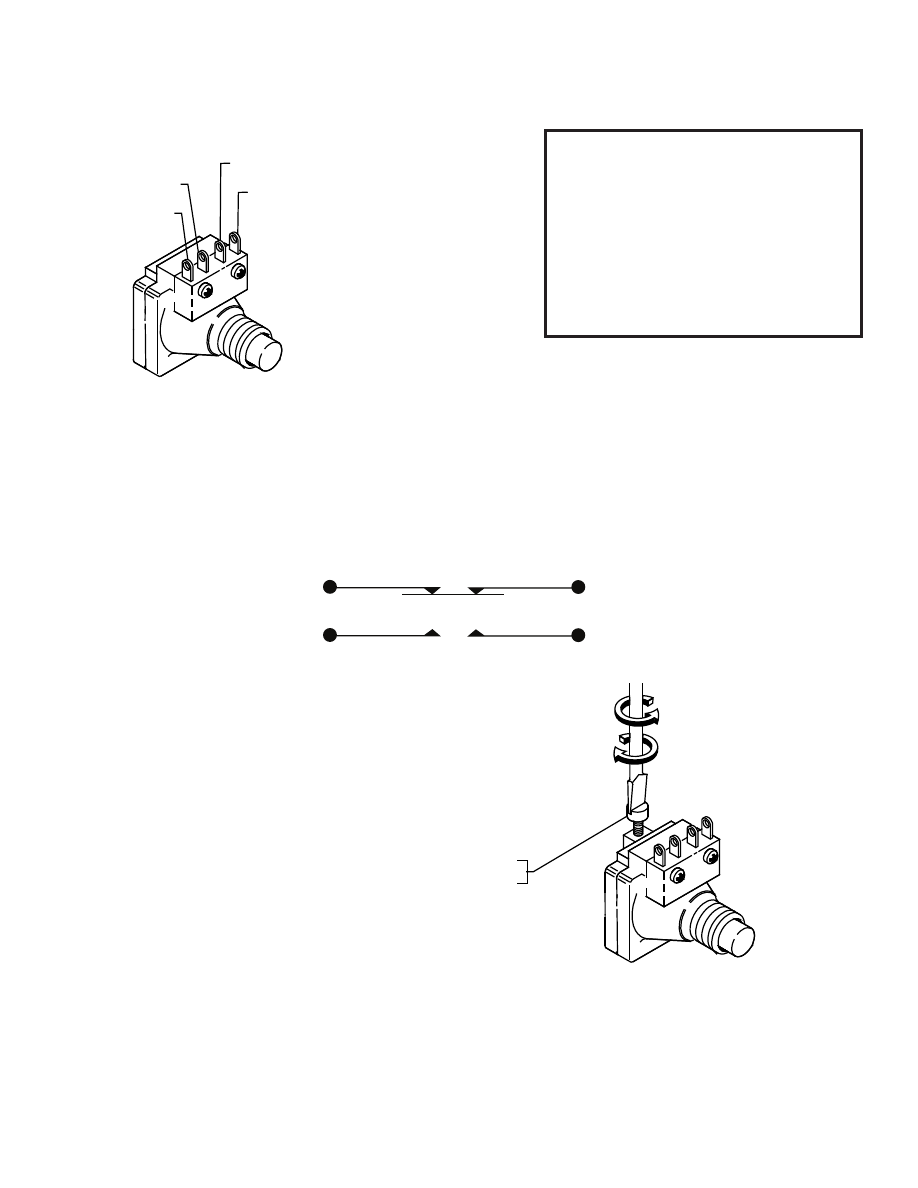
CONTACT DIAGRAM
SWITCH INFORMATION
- 5 -
CONTACTS
One set NO and one set NC
LEAD WIRE COLORS
IN PARENTHESIS.
QTY. PART No. NAME
P
4
1 1
1 2
1
QTY. PART No. NAME
P
3
3
4
1 1
1 2
1
8 x 1
A
IS NOT USED
1
(BLACK) NC
(RED) NO
NC (GREEN)
NO (WHITE)
QTY. PART No. NAME
P
3
4
1 1
1 2
1
6-32 x 1. 00
1
SETTING – 25 TO 45 SECONDS
F
QTY. PART No. NAME
P
3
3
4
1 1
1 2
1
12
9
IS NOT USED
1
6-32 x 1. 00
1
NC
NO
NC
NO
BUTTON ACTIVATED
M
COUNTERCLOCKWISE
CLOCKWISE
TIMER RANGE ADJUSTMENT SCREW
ADJUSTMENT RANGE - 2 TO 60 SECONDS
TIMER FACTORY SET TO MINIMUM TIME
SETTING. TO INCREASE TIME, TURN
SCREW CLOCKWISE IN 1/4 TURN
INCREMENTS. WHEN CLOSE TO DESIRED
TIME, TURN SCREW IN VERY FINE
INCREMENTS TO DESIRED SETTING.
CAUTION: OVER-TIGHTENING MAY
CAUSE DAMAGE TO TIMER.