PULS ML95.100 User Manual
Page 4
ML100 Instruction Manual for Power Supplies
ML100 Bedienungsanleitung für Stromversorgung
CE Marking
CE mark is in conformance with EMC directive 2004/108/EC, the low-voltage directive (LVD)
2006/95/EC and the RoHS directive 2011/65/EU.
EMC Immunity: EN 61000-6-1, EN 61000-6-2
EMC Emission EN 61000-6-3, EN 61000-6-4, FCC Part 15 Class B
CE Kennzeichnung
Das CE Zeichen ist angebracht und erklärt die Erfüllung der EMV Richtlinie 2004/108/EG, der
Niederspannungsrichtlinie 2006/95/EG und der RoHS Richtlinie 2011/65/EU.
Störfestigkeit: EN 61000-6-1, EN 61000-6-2
Störaussendung: EN 61000-6-3, EN 61000-6-4, FCC Part 15 Klasse B
Terminals and Wiring
(see Fig. 8)
Use appropriate copper cables that are designed for a minimum operating temperature of:
60°C for ambient temperatures up to 45°C,
75°C for ambient temperatures up to 60°C and
90°C for ambient temperatures up to 70°C.
Follow national installation codes and regulations! Ensure that all strands of a stranded wire enter
the terminal connection! Ferrules are allowed. Unused terminal must be closed.
Solid wire / Stranded wire / AWG:
0.3-2.5mm
2
/ 0.3-2.5mm
2
/ AWG26-12
Max. wire diameter:
2.25mm (including ferrules)
Wire stripping length:
6mm / 0.25inch
Anschlussklemmen und Verdrahtung
(siehe Bild 8)
Verwenden Sie geeignete Kupferkabel, die mindestens für:
60°C bei einer Umgebungstemperatur bis zu 45°C,
75°C bei einer Umgebungstemperatur bis zu 60°C und
90°C bei einer Umgebungstemperatur bis zu 70°C zugelassen sind.
Aderendhülsen sind erlaubt. Nationale Bestimmungen und Installationsvorschriften beachten!
Achten, dass keine einzelnen Drähte von Litzen abstehen. Nichtbenutzte Klemmen schließen.
Starrdraht / Litze / AWG:
0,3-2,5mm
2
/ 0,3-2,5mm
2
/ AWG26-12
Maximaler Drahtdurchmesser:
2,25mm (inklusive Aderendhülsen)
Abisolierlänge
6mm
/
0,25inch
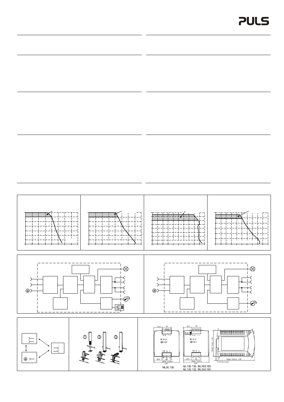
Output- and Overload Characteristic
(see Fig. 1 to 4)
The units are overload, no-load, short-circuit proof.
The units are equipped with a “Single Use/ Parallel Use” feature (except ML95.100). The “Parallel
Use” mode regulates the output voltage in such a manner that the voltage at no load is approx.
4% higher than at nominal load. For parallel use adjusted the output voltage to the same value
(±100mV) in “Single mode” at the same load condition on all units, or leave the factory settings.
Afterwards, the jumper on the front of the unit shall be moved from “Single Use” to “Parallel Use”,
in order to achieve a load sharing.
If no jumper is plugged in, the unit is in “Single Use”. Factory setting is “Single Use”.
Overload characteristic:
Above the rated output current, the output voltage will decrease as a result of the output current
limitation. The current flows continuously. No hiccup or shut-down behaviour.
Ausgangs- und Überlastverhalten
(siehe Bild 1 bis 4)
Die Geräte sind leerlauf-, überlast- und kurzschlussfest.
Die Geräte sind mit einem “Single Use/ Parallel Use” Jumper ausgestattet (außer ML95.100). In
„Parallel Use“ ist die Ausgangsspannung so geregelt, dass diese im Leerlauf um etwa 4% höher
ist als bei Nennlast. Bei Parallelschaltung von Geräten die Ausgangsspannung aller Geräte bei
gleicher Belastung im „Single Mode“ auf ±100mV genau einstellen, oder auf Werkseinstellung
belassen. Danach die Steckbrücke an der Front des Gerätes von „Single Use“ auf „Parallel Use“
umstecken, um eine Aufteilung des Laststromes zwischen den Geräten zu erreichen.
Ein nicht eingesteckter Jumper bedeutet „Single Use“. Werkseinstellung ist „Single Use“.
Überlastverhalten:
Wird der Nennstrom überschritten, sinkt die Spannung aufgrund der Strombegrenzungs-
eigenschaft. Der Strom fließt ununterbrochen weiter, kein Hiccup oder Abschaltverhalten.
Dielectric Strength
(see Fig. 7)
The output voltage is floating and separated from the input according to SELV (IEC/EN 60950-1)
and PELV (EN 60204-1, EN 50178; IEC 62103, IEC 60364-4-41) requirements. Type and factory
tests are conducted by the manufacturer. Field tests may be conducted in the field using the
appropriate test equipment which applies the voltage with a slow ramp (2s up and 2s down).
Connect all phase-terminals together as well as all output poles before the test is conducted.
When testing, set the cut-off current settings to the value in the table below.
A B
C
Type Test (60s)
2500Vac
3000Vac
500Vac
Factory Test (5s)
2500Vac
2500Vac
500Vac
Field Test (5s)
2000Vac
2000Vac
500Vac
Cut-off current setting
>6mA
>6mA
>20mA
Isolationsfestigkeit
(siehe Bild 7)
Die Ausgangsspannung hat keinen galvanischen Bezug zur Erde oder Schutzleiter und ist zum
Eingang nach den SELV (IEC/EN 60950-1) und PELV (EN 60204-1, EN 50178, IEC 62103, IEC
60364-4-41) Standards getrennt. Typ- und Stückprüfungen werden beim Hersteller durchgeführt.
Wiederholungsprüfungen dürfen mittels geeigneten Prüfgenerators mit langsam (2s)
ansteigenden und abfallenden Spannungsrampen in der Anwendung erfolgen. Vor den Tests sind
alle Phasen wie auch alle Ausgangspole miteinander zu verbinden. Während der Tests darf die
Strom- Abschaltschwelle nicht kleiner als der in der Liste angegebene Wert sein.
A B C
Typprüfung (60s)
2500Vac
3000Vac
500Vac
Stückprüfung (5s)
2500Vac
2500Vac
500Vac
Wiederholungsprüfung (5s)
2000Vac
2000Vac
500Vac
Strom- Abschaltschwelle >6mA >6mA >20mA
Fig. 1 / Bild 1
ML95.101: Output Characteristic /
Ausgangskennlinie, typ
Fig. 2 / Bild 2
ML100.100, ML100.109: Output Characteristic /
Ausgangskennlinie, „Single Use“, typ.
Fig. 3 / Bild 3
ML100.102: Output Characteristic /
Ausgangskennlinie, „Single Use“, typ.
Fig. 4 / Bild 4
ML100.105: Output Characteristic /
Ausgangskennlinie, „Single Use“, typ.
Output Voltage
0
0
2
4
4
8
12
28V
16
20
24
8A
5
3
1
6
7
Adjustment
Range
Output
Current
Output Voltage
0
0
2
4
4
8
12
28V
16
20
24
8A
5
3
1
6
7
Adjustment
Range
Output Current
Output Voltage
0
0
2
4
2
4
6
16V
8
12
14
10A
5
3
1
6
7
10
8
9
Adjustment
Range
Output Current
Output Voltage
0
0
1
2
10
20
60V
30
50
5A
2.5
1.5
0.5
3 3.5
40
4 4.5
Adjustment
Range
Output Current
Fig. 5 / Bild 5
ML100.100, ML100.102, ML100.105, ML100.109: Functional Diagram / Funktionsschaltbild
Fig. 6 / Bild 6
ML95.100: Functional Diagram / Funktionsschaltbild
Input Fuse
&
Input Filter
L
N
Output Over-
Voltage
Protection
115/230V
Auto Select
Input
Rectifier
&
Inrush
Limiter
Power
Converter
Output
Voltage
Regulator
+
+
-
-
Output
Filter
V
OUT
DC
ok
Single /
Parallel
Input Fuse
&
Input Filter
L
N
Output Over-
Voltage
Protection
115/230V
Auto Select
Input
Rectifier
&
Inrush
Limiter
Power
Converter
Output
Voltage
Regulator
+
+
-
-
Output
Filter
V
OUT
DC
ok
Fig. 7 / Bild 7
Insulation / Isolation
Fig. 8 / Bild 8
Connecting a wire / Anschluss eines Drahtes
Fig. 9 / Bild 9
Physical Dimensions / Abmessungen
A
C
N
L
Input
Earth, PE
Output
-
+
B
PU-328.013.00-10A