PULS UC10.241 User Manual
Page 4
EDLC Buffer Module Instruction Manual
Bedienungsanleitung für EDLC Puffermodule
Installation
Mount the unit onto a DIN-rail according to EN 60715 (7.5 or 15mm height) so that the power
terminals are located on the top of the unit. Do not obstruct air flow as the unit is convection
cooled. Ventilation grid must be kept free of any obstructions. The following installation clearances
must be kept when the buffer module is permanently fully loaded:
Left / right: 5mm (15mm in case the adjacent device is a heat source)
40mm on top, 20mm on the bottom of the unit.
Use in hazardous location areas
Units which are marked with "Class I Div 2" are suitable for use in Class I Division 2 Groups A, B,
C, D locations.
Units which are marked with
II 3G Ex nA nC IIC T4 Gc are suitable for use in Group II
Category 3 (Zone 2) environments and are evaluated according to EN 60079-0:2009 and EN
60079-15:2010.
WARNING EXPLOSION HAZARDS!
Substitution of components may impair suitability for this environment. Do not disconnect the unit
unless power has been switched off or the area is known to be non-hazardous. A suitable
enclosure must be provided for the end product which has a minimum protection of IP54 and fulfils
the requirements of the EN 60079-15:2010.
Installation
Das Gerät auf eine DIN-Schiene entsprechend EN 60715 (7,5 oder 15mm Höhe) so montieren,
dass sich die Leistungsanschlüsse oben befinden. Das Gerät ist für Konvektionskühlung
ausgelegt, daher Luftzirkulation nicht behindern! Folgende Einbauabstände sind bei dauerhafter
Volllast einzuhalten:
Links / rechts: 5mm (15mm bei benachbarten Wärmequellen)
Oben: 40mm, unten 20mm vom Gerät.
Betrieb in explosionsgefährdeter Umgebung
Geräte, die mit "Class I Div 2" gekennzeichnet sind, sind für den Einsatz in Klasse I Division 2
Gruppen A,B,C,D Umgebung geeignet.
Geräte, die mit
II 3G Ex nA nC IIC T4 Gc, gekennzeichnet sind, sind nach EN 60079-0:2009
und EN 60079-15:2010 getestet und können in Gruppe II, Kategorie 3 (Zone 2) Umgebungen
verwendet werden.
ACHTUNG EXPLOSIONSGEFAHR!
Veränderungen am Gerät können die Tauglichkeit für diese Umgebung beeinträchtigen.
Anschlüsse nicht abklemmen, solange Spannung anliegt oder die Umgebung als
explosionsgefährlich gilt. Das Gerät muss mindestens in ein IP54 Gehäuse, welches den
Anforderungen der EN 60079-15:2010 entspricht, eingebaut werden.
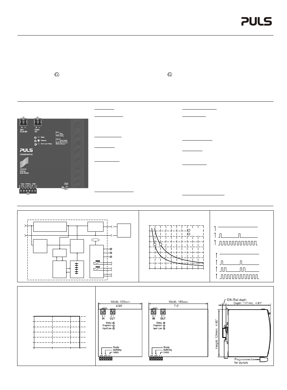
User Interface
A Power
Port (Quick-connect spring-clamp terminals)
To connect the input power and the buffered loads
B Signal
Connector (pluggable screw terminal)
- Ready: Contact is closed when status LED shows “Ready”
- Buffering: Contact is closed during buffering
Contact ratings: max. 60Vdc 0.3A, 30Vdc 1A, 30Vac 0.5A
- Inhibit input: A voltage between 10 and 35V applied on
this input signal disables buffering (e.g. during service)
C Chassis
Ground (screw)
Use a M4 ring-type terminal to connect the housing to
ground, when required
D Status
LED (green, see figure 3 for flashing pattern)
- Ready: Capacitors fully charged, no failures detected
- Charging: Capacitors being charged
- Buffering: Capacitors being discharged
D Diagnosis
LED (yellow, see figure 3 for flashing pattern)
- Current Overload: Too high output current, output voltage
falls below 20Vdc, ready contact opens
- High Temperature: Indicates a capacitor temperature
higher than 65°C, charging and buffering remains possible,
ready contact opens.
- Buffer Time Expired: Buffering stopped due to
discharged capacitors
- Inhibit Active: Buffering is blocked by the inhibit signal
E Check Input Voltage LED (red)
Indicates a too low or too high input voltage. The input
voltage must be between 23Vdc and 30Vdc to turn-on the
output and to start charging of capacitors.
Benutzerinterface
A Leistungsanschlüsse (Schnellanschluss Federkraftklemmen)
Zum Anschluss der Versorgung und der gepufferten Verbraucher
B Signalstecker (steckbare Schraubklemme)
- „Ready“: Kontakt ist geschlossen, wenn die Status LED “Ready”
anzeigt
- „Buffering“: Kontakt ist im Pufferbetrieb geschlossen
Kontaktbelastbarkeit: max. 60Vdc 0,3A, 30Vdc 1A, 30Vac 0,5A
- „Inhibit input“: Eine Spannung zwischen 10 und 35V an diesem
Eingang verhindert einen Pufferbetrieb (z.B. bei Servicearbeiten)
C „Chassis
Ground“ (Schraube)
Wenn erforderlich, kann hier das Gehäuse mit einem M4
Ringkabelschuh geerdet werden.
D Status
LED (grün, siehe Bild 3 für Blinkmuster)
- „Ready“: Kondensatoren voll geladen, keine Fehler erkannt
- „Charging“: Kondensatoren werden geladen
- „Buffering“: Kondensatoren werden entladen
D Diagnose
LED (gelb, siehe Bild 3 für Blinkmuster)
- „Current Overload“: Zu hoher Ausgangsstrom,
Ausgangsspannung kleiner 20Vdc, Ready Kontakt ist offen.
- „High Temperature“: Zeigt an, wenn die Temperatur der
Kondensatoren größer 65°C ist, Lade- und Pufferbetrieb ist
möglich, Ready Kontakt ist offen.
- „Buffer Time Expired“: Puffermodus wurde beendet, nachdem
die Kondensatoren komplett entladen waren.
- „Inhibit Active“: Ein aktiviertes Signal verhindert Pufferbetrieb
E „Check Input Voltage“ LED (rot)
Zeigt eine zu geringe oder zu hohe Eingangsspannung an. Die
Spannung muss zwischen 23Vdc und 30Vdc sein, um den
Ausgang einzuschalten und den Ladevorgang zu starten.
Fig. 1 / Bild 1
Functional Diagram / Funktionsschaltbild
Fig. 2 / Bild 2
Buffer Time / Pufferzeit
Fig. 3 / Bild 3
Flashing Pattern / Blinkmuster
-
+
Boost
Converter
(Step-up
Converter)
Charger
Balancing
&
Safety
Circuits
Input
Electronic
Current
Limiter
+
-
Buffered
Load
Output
Diagnosis LED
(yellow)
Status LED
(green)
+
Controller
Input Low
(red)
Buffering Contact
Ready Contact
(7)
-
(8)
(1)
(2)
(3)
(4)
Capacitors
Input Fuse,
Reverse Polarity Protection,
Return Current Protection
Temp
Input
Voltage
Monitor
Inhibit
Buffer Current
0
20
200s
40 60 80 100 120 140 160 180
Buffer Time
a
b
0
6A
4A
16A
8A
2A
10A
12A
14A
UC10.241
UC10.242
a
b
Flashing Pattern for green status LED
Ready
1
0
1
0
Charging
1
0
Buffering
Flashing Pattern for yellow diagnosis LED
1
0
Current
Overload
1
0
High
Temperature
1
0
Buffer time
expired
1
0
Inhibit
active
Fig. 4 / Bild 4
Operational Temperature Range/
Arbeitstemperaturbereich
Fig. 5 / Bild 5
Dimensions / Abmessungen
UC10.241 UC10.241 UC10.241, UC10.242
0
-40
0
+40
+60°C
2.5
5.0
7.5
10.0
12.5
15A
Ambient Temperature
Allowable Output Current
PU-406.010.00-10A