PULS UC10.241 User Manual
Page 3
EDLC Buffer Module Instruction Manual
Bedienungsanleitung für EDLC Puffermodule
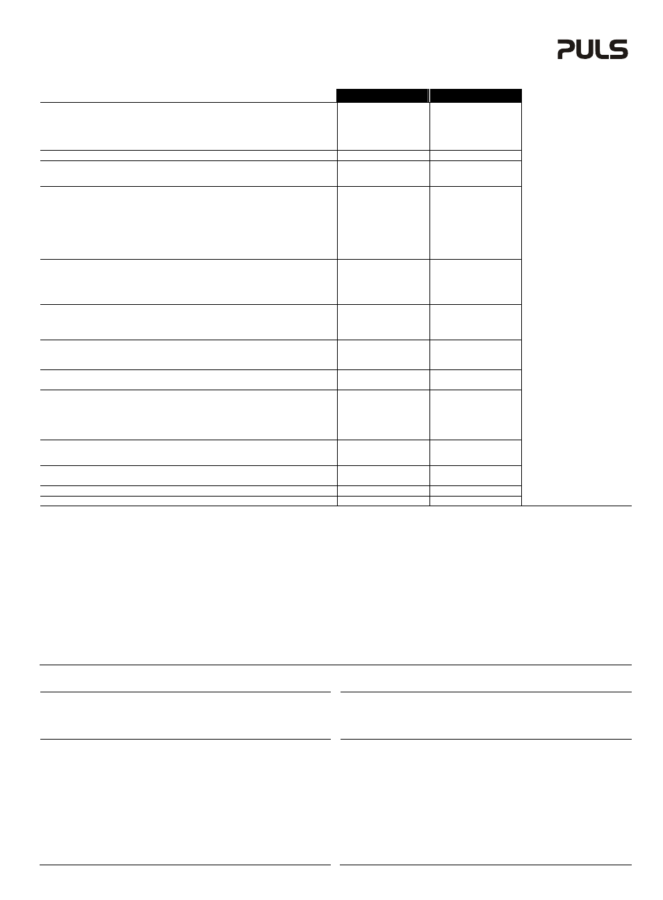
Technical Data
1)
Technische
Daten
1)
UC10.241
UC10.242
Input Voltage
Eingangsspannung
nom.
DC 24-28V
-20%/+25%
DC 24-28V
-20%/+25%
Input Voltage Range
Eingangsspannungsbereich
min.
min.
22.5 – 30Vdc
2)
19.2 - 35Vdc
3)
22.5 – 30Vdc
2)
19.2 - 35Vdc
3)
Turn-on Voltage
Einschaltspannung
typ. / max.
22.8V / 23.0V
22.8V / 23.0V
Input Current
4)
Eingangsstrom
4)
max.
0.1A / 1.3A / 17A
0.1A / 1.3A / 17A
Return Current to Input
5)
Rückwärtsstrom in den Eingang
5)
max.
-11mA
-11mA
Transfer Threshold Voltage
6)
Schwellspannung für Pufferbetrieb
6)
typ.
22.45V (0A load)
22.55V (10A load)
22.60V (15A load)
22.45V (0A load)
22.55V (10A load)
22.60V (15A load)
Output Voltage
in Normal Mode Ausgangsspannung
Normalbetrieb
nom.
Input – 0.3V (10A load)
Input – 0.45V (15A load)
Input – 0.3V (10A load)
Input – 0.45V (15A load)
in Buffer Modes
Pufferbetrieb
typ.
22.45V (0A buffer current)
22.25V (10A buffer current)
22.12V (15A buffer current)
22.45V (0A buffer current)
22.25V (10A buffer current)
22.12V (15A buffer current)
Output Current
Ausgangsstrom
nom.
15A
15A
Output Power
Ausgangsleistung
nom.
360W
360W
Output Overload Behavior
Überlastverhalten am Ausgang
-
continuous current
continuous current
Capacitor Size
Größe der Kondensatoren
nom.
6kWs
12kWs
Charging Time
Ladezeit
16 minutes
32 minutes
Buffer Time
Pufferzeit
200s at 1A
16.5s at 10A
9s at 15A
400s at 1A
33s at 10A
18s at 15A
Efficiency Wirkungsgrad
typ.
97.8%
97.8%
Power Losses
Verlustleistung
typ.
2.9A (0A load)
5.5A (10A load)
7.7A (15A load)
2.9A (0A load)
5.5A (10A load)
7.7A (15A load)
Operational Temperature Range Betriebstemperaturbereich
nom.
-40°C - +60°C
-40°C - +60°C
Storage Temperature Range
Lagertemperaturbereich
nom.
-40°C - +70°C
-40°C - +70°C
Humidity
7)
Feuchte
7)
IEC 60068-2-30
5 - 95% r.H.
5 - 95% r.H.
Vibration Schwingen IEC 60068-2-6
2g
10)
2g
10)
Shock Schocken
IEC 60068-2-27
30g 6ms, 20g 11ms
10)
30g 6ms, 20g 11ms
10)
Degree of Pollution
Verschmutzungsgrad
IEC 62103
2
7)
2
7)
Degree of Protection
Schutzart
EN 60529
IP20
IP20
Class of Protection
Schutzklasse
IEC 61140
III
III
Over-temperature Protection
Übertemperaturschutz
OTP
Yes / Ja
Yes / Ja
Output Over-voltage Protection Überspannungsschutz
am
Ausgang
OVP, max.
35Vdc
35Vdc
Parallel Use for higher currents
for
redundancy
for longer buffer times
Parallel schaltbar für höhere Ströme
zur
Redundanz
längere
Pufferzeiten
-
-
-
No / Nein
Yes / Ja
Yes / Ja
No / Nein
Yes / Ja
Yes / Ja
Dimensions
9)
(WxHxD) Abmessungen
9)
(BxHxT)
nom.
126x124x117mm
198x124x117mm
Weight Gewicht
max.
1150g, 2.54lb
1720g, 3.79lb
Approvals Zulassungen
-
Ж 8)
Ж 8)
Limited Warranty
Eingeschränkte Gewährleistung
Years / Jahre
3
3
1) All parameters are specified at 24Vdc input voltage, nominal output current, 25°C ambient
and after a 5 minutes run-in time unless otherwise noted.
2) Describes the voltage range where capacitors get charged and buffering is possible
3) Describes the voltage range where indicators and signaling are working
4) Capacitors charged and output not loaded / during charging and output not loaded / during
charging and output loaded with nominal current
5) Leakage current to input in buffer mode
6) The transfer threshold voltage describes the input voltage, where the unit switches into buffer
mode and delivers output voltage from the capacitors if the input was above the turn-on level
before and all other buffer conditions are fulfilled. The unit switches back to normal mode, as
soon as the input voltage exceeds the transfer threshold voltage again.
7) Do not energize while condensation is present.
8) See datasheet or markings on the unit.
9) Depth without DIN-rail
10) Higher levels possible when utilizing the wall mounting bracket ZM2.WALL
1) Alle Werte gelten bei 24Vdc Eingangsspannung, Nennausgangsstrom, 25°C Umgebung und
nach einer Aufwärmzeit von 5 Minuten, falls nichts anderes angegeben.
2) Beschreibt den Spannungsbereich, bei dem die Kondensatoren geladen werden und eine
Pufferung stattfinden kann.
3) Beschreibt den Spannungsbereich, bei dem die Signalisierung und Anzeigeelemente
arbeiten.
4) Kondensatoren geladene und Ausgang nicht belastet / Kondensatoren werden geladen und
Ausgang nicht belastet / Kondensatoren werden geladen und Ausgang mit Nennstrom
belastet
5) Leckstrom in den Eingang während des Pufferbetriebs
6) Die Schwellspannung für den Pufferbetrieb beschreibt de Eingangsspannung, bei dem das
Gerät in den Pufferbetrieb umschaltet und die Energie aus den Kondensatoren zur Verfügung
stellt. Vorher musste der Eingang über der Einschaltspannung gewesen sein, und alle
weiteren Pufferbedingungen erfüllt gewesen sein. Das Gerät schaltet wieder in den
Normalbetrieb, sobald die Eingangsspannung diesen Schwellwert übersteigt.
7) Nicht betreiben, solange das Gerät Kondensation aufweist.
8) Siehe Datenblatt oder Prüfzeichen auf dem Gerät.
9) Tiefe ohne DIN-Schiene
10) Höhere Werte sind bei Verwendung des Wandmontageadapters ZM2.WALL möglich
CE Marking
CE mark is in conformance with EMC directive 2004/108/EC, the low-voltage directive (LVD)
2006/95/EC and the RoHS directive 2011/65/EC.
EMC Immunity: EN 61000-6-1, EN 61000-6-2
EMC Emission EN 61000-6-3, EN 61000-6-4, FCC Part 15 Class B
CE Kennzeichnung
Das CE Zeichen ist angebracht und erklärt die Erfüllung der EMV Richtlinie 2004/108/EG, der
Niederspannungsrichtlinie 2006/95/EG und der RoHS Richtlinie 2011/65/EG.
Störfestigkeit: EN 61000-6-1, EN 61000-6-2
Störaussendung: EN 61000-6-3, EN 61000-6-4, FCC Part 15 Klasse B
Terminals and Wiring
Use appropriate copper cables that are designed for a minimum operating temperature of:
60°C for ambient temperatures up to 45°C,
75°C for ambient temperatures up to 60°C and
90°C for ambient temperatures up to 70°C.
Follow national installation codes and regulations! Ensure that all strands of a stranded wire enter
the terminal connection! Ferrules are allowed.
Input / Output
Signals
Spring-clamp terminal
Plug-connector
Solid
wire
0.5-6mm
2
0.2-1.5mm
2
Stranded
wire
0.5-4mm
2
0.2-1.5mm
2n
American wire gauge
AWG 20-10
AWG 22-14
Max. wire diameter (including ferrules)
2.8mm
1.5mm
Wire stripping length
10mm / 0.4inch
6mm / 0.24inch
Tightening torque
N/A
0.4Nm / 3.5lb.inch
Anschlussklemmen und Verdrahtung
Verwenden Sie geeignete Kupferkabel, die mindestens für:
60°C bei einer Umgebungstemperatur bis zu 45°C,
75°C bei einer Umgebungstemperatur bis zu 60°C und
90°C bei einer Umgebungstemperatur bis zu 70°C zugelassen sind.
Beachten Sie nationale Bestimmungen und Installationsvorschriften! Stellen Sie sicher, dass
keine einzelnen Drähte von Litzen abstehen. Aderendhülsen sind erlaubt.
Eingang / Ausgang
Signale
Federkraftklemme Steckverbinder
Starrdraht
0,5-6mm
2
0,2-1,5mm
2
Litze
0,5-4mm
2
0,2-1,5mm
2
AWG
AWG 20-10
AWG 22-14
Max. Drahtdurchmesser (inkl. Aderendhülsen) 2,8mm
1,5mm
Abisolierlänge
7mm / 0,28inch
6mm / 0,24inch
Anzugsdrehmoment
nicht zutreffend
0,4Nm / 3,5lb.inch