PULS QTD20.241 User Manual
Page 4
QTD20 Power Supply Instruction Manual
QTD20 Bedienungsanleitung für Stromversorgung
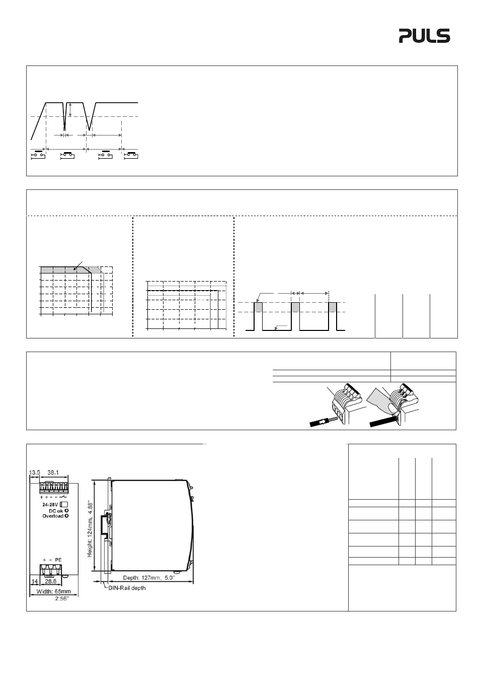
DC-ok Relay Contact /
DC-ok Relais Kontakt
250ms
90%
V
ADJ
<
1ms
10%
open
V
OUT
= V
ADJ
open
closed
closed
>
1ms
This feature monitors the output voltage, which is produced by the
power supply, and is independent of a return voltage from a unit
which is connected in parallel.
Contact closes when the output voltage reaches the adjusted value
after turn-on of the power supply or when the output
voltage reaches 90% after a dip of the output.
Contact opens when the output voltage dips more than 10%.
Short dips will be extended to a length of 250ms.
Dips shorter than 1ms will be ignored.
Contact ratings max.: 42Vdc 0.3A, 30Vdc 1A,
30Vac 0.5A, Resistive load
min.: 1mA
Please note:
After turn-on of the power supply, the output voltage has to reach the
adjusted level before the DC-ok relay contact closes and the green
DC-ok LED turns on. If this level cannot be achieved, the red
overload LED will stay on. This is an important condition to consider
particularly, if the load is a battery or the power supply is used for
N+1 redundant systems.
Diese Funktion überwacht die vom Gerät erzeugte
Ausgangsspannung und lässt sich von einer rückwärts eingespeisten
Spannung nicht beeinflussen (z.B.: Batterieladung oder
Parallelschaltung)
Kontakt schließt sobald nach dem Einschalten der Ausgang den
eingestellten Wert erreicht oder wenn nach einem
Einbruch des Ausgangs die Spannung wieder
> 90% des eingestellten Wertes wird.
Kontakt öffnet sobald der Ausgang um mehr als 10% einbricht.
Kurze Einbrüche werden auf 250ms verlängert.
Einbrüche kürzer 1ms werden ignoriert.
Belastbarkeit max.: 42Vdc 0.3A, 30Vdc 1A, 30Vac 0.5A, (R-Last)
min.: 1mA
Zu beachten:
Nach dem Einschalten der Stromversorgung muss die eingestellte
Ausgangsspannung erreicht werden, damit der DC-ok Signalkontakt
schließt und die DC-ok LED angeht. Wird dieser Wert nicht erreicht,
leuchtet die Overload LED. Dies kann bei Batterieladeanwendungen
oder bei N+1 redundanten Systemen von Bedeutung sein.
Output and Overload Characteristic
The unit is designed to support loads with a higher short-term power requirement without
damage. The unit can deliver up to 720W output power for a defined period of time (Bonus
time) before it reduces the output power automatically to 480W.
Ausgangs- und Überlastverhalten
Die Stromversorgung ist zur Versorgung von Lasten mit kurzzeitig hohem Bedarf an Spitzenleistung
konstruiert und nimmt dabei keinen Schaden. Die Stromversorgung kann für eine bestimmte Zeit
(Bonuszeit) bis zu 720W Ausgangsleistung liefern, bevor automatisch auf 480W zurückgeregelt wird.
Bonus time
Defines the duration until the output
voltage starts dipping when more than
480W is drawn (controlled by software).
Bonuszeit
Gibt die Dauer an bis die Ausgangs-
spannung sinkt, wenn mehr als 480W
entnommen werden. (softwaregesteuert).
Repetitive pulse loading
Multiple pulses can be supported as long as the average (R.M.S.) output current stays below the
specified continuous output current. If it is higher, the unit will respond with a thermal shut-down after
a period of time.
Periodische pulsförmige Belastung
Die Stromversorgung kann regelmäßig und periodisch mit Pulsen belastet werden, solange der
entnommene Mittelwert des Ausgangsstromes (R.M.S.) unterhalb des Nennwertes liegt. Wenn der
entnommene Strom höher ist, kann es zu einer thermischen Abschaltung kommen.
Examples for pulse load compatibility /
Beispiele für mögliche Pulsstrom Lastspiele
P
PEAK
P
0
T
PEAK
T
0
600W 480W 1s
>25s
600W 0W 1s >1.3s
600W 240W 0.1s >0.16s
600W 240W 1s >1.6s
Output characteristic (typ.)
Ausgangskennlinie (typ.)
Output Voltage
0
0
5
10
20
25
4
8
12
28V
16
20
24
15
30A
Output Current
sh
o
rt
-te
rm
Adjustment
Range
co
n
tin
u
o
u
s
max.
Bonus Time
0
105
110
115
120
125
130%
Output Power
1
2
3
4
5s
min.
100%
P
PEAK
T
PEAK
P
0
T
0
max.
125%
600W 240W 3s >4.9s
Solid wire
Starrdraht
0.5-6mm
2
Stranded wire
Litze
0.5-4mm
2
American wire gauge
AWG
AWG 20-10
Wire stripping length
Abisolierlänge
10mm / 0.4inch
Pull-out force (UL 486E) Abziehkraft (UL 486E) 10AWG: 80N 12AWG: 60N
Terminals and Wiring
The power supplies are equipped with quick-
connect spring-clamp terminals. Use
appropriate copper cables that are designed
for following minimum operating temperatures:
Input:
60°C for an ambient up to 45°C,
75°C for an ambient up to 60°C,
Output:. 75°C for an ambient up to 40°C,
95°C for an ambient up to 60°C.
Follow national installation codes and
regulations. Ensure that all strands of a
stranded wire enter the terminal connection.
Ferrules are allowed, but not required.
Anschlussklemmen und Verdrahtung
Die Stromversorgungen sind mit Schnellanschluss-
Federkraftklemmen ausgestattet. Verwenden Sie
geeignete Kupferkabel, die mindestens für folgende
Betriebstemperaturen geeignet sind:
Eingang: 60°C für Umgebungstemperaturen bis 45°C,
75°C für Umgebungstemperaturen bis 60°C,
Ausgang:. 75°C für Umgebungstemperaturen bis 40°C,
95°C für Umgebungstemperaturen bis 60°C.
Beachten Sie nationale Bestimmungen und
Installationsvorschriften! Stellen Sie sicher, dass keine
einzelnen Drähte von Litzen abstehen. Aderendhülsen
sind erlaubt, aber nicht erforderlich.
Physical Dimensions / Abmessungen
Indicator / Anzeigelampen
Overlo
ad LED
DC-ok
LE
D
DC-ok Contact
Normal mode
OFF
ON
Closed
At 100-125%
overload for < 4s
OFF
ON
Closed
Overload
(V
OUT
< 90%)
ON
OFF
Open
Short-circuit
(V
OUT
= ca. 0V)
ON
OFF
Open
Over- temperature
ON OFF
Open
No input power
OFF OFF
Open
Installation:
An appropriate electrical and fire end-product enclosure
should be considered in the end use application. Use DIN-
rails according to EN 60715 or EN 50022 with a height of 7.5
or 15mm. Mounting orientation must be with output terminals
on top and input terminals on the bottom. For other
orientations see datasheet. Do not obstruct air flow as the unit
is convection cooled. Ventilation grill must be kept free of any
obstructions. The following installation clearances must be
kept when the power supply is permanently fully loaded:
Left / right: 5mm (15mm in case the adjacent
device is a heat source)
40mm on top, 20mm on the bottom
Installation:
Das Umgehäuse dieser Einbaustromversorgung muss für
Elektrogeräte geeignet sein und einen geeigneten Schutz
gegen eine Ausbreitung von Feuer bieten.
Geeignet für DIN-Schienen entsprechend EN 60715 oder EN
50022 mit einer Höhe von 7,5 oder 15mm. Der Einbau hat so
zu erfolgen, dass sich die Eingangsklemmen unten und die
Ausgangsklemmen oben befinden. Für andere Einbaulagen
siehe Datenblatt. Luftzirkulation nicht behindern! Das Gerät
ist für Konvektionskühlung ausgelegt. Es ist für ungehinderte
Luftzirkulation zu sorgen. Folgende Einbauabstände sind bei
dauerhafter Volllast einzuhalten:
Links / rechts: 5mm (15mm bei benachbarten
Wärmequellen)
Oben: 40mm, unten 20mm
The DC-ok LED and the DC-ok contact
functions are synchronized.
Die DC-ok LED und der DC-ok Relaiskontakt
arbeiten synchron.
PU-367.010.00-10A