PULS QT40.241 User Manual
Page 5
QT40 Instruction Manual for Power Supplies
QT40 Bedienungsanleitung für Stromversorgung
Fig. 1/ Bild 1
Output Characteristic / Ausgangskennlinie, typ.
Fig. 2/ Bild 2
BonusPower
®
Time / BonusPower
®
Zeit
Fig. 3/ Bild 3
Insulation / Isolation, typ.
Output Current
0V
0
50%
100%
4V
8V
12V
28V
16V
20V
24V
150%
200%
250%
24V
Unit
0V
6V
12V
18V
42V
24V
30V
36V
36V
Unit
0V
8V
16V
24V
56V
32V
40V
48V
48V
Unit
Adjustment range
A
B
A
B
Short-term (4s)
available
Continuously
available
Output Voltage
max.
Bonus Time
0
110
120
130
140
150
160%
1
2
3
4
5s
min.
Output Power
A
D
C
B
B
L1
Input
DC-ok
Earth
Output
-
+/-
Shut-down
L3
L2
Fig. 4 / Bild 4
DC-OK-Signal
Fig. 5 / Bild 5
Output derating for 3-Phase operation/
Leistungsrücknahme bei 3-Phasenbetrieb
Fig. 6 / Bild 6
Output derating for 2-Phase operation /
Leistungsrücknahme bei 2-Phasenbetrieb
250ms
90%
V
ADJ
<
1ms
10%
open
V
OUT
= V
ADJ
open
closed
closed
>
1ms
Allowed Output Power 3-Phase Operation
0
-25
0
20
40
70°C
240W
480W
120W
960W
1200W
1440W
cont inuous
60
Ambient Temperature
short -t erm (4s)
Allowed Output Power 2-Phase Operation
0
-25
0
20
40
70°C
240W
480W
120W
960W
1200W
1440W
60
Ambient Temperature
A... 2x 340 to 460Vac
B... 2x 460 to 552Vac
C... max. 60 seconds
D... max. 4 seconds
A
B
C
D
Fig. 7 / Bild 7
Remote Control of Output Voltage / Externe Steuerung der Ausgangsspannung
Fig. 8 / Bild 8
Shut-down Input / Shut-down Eingang
Control Voltage
14V
0V
5V
10V
16V
18V
20V
28V
22V
24V
26V
15V
20V
24V
Unit
21V
24V
27V
30V
42V
33V
36V
39V
36V
Unit
28V
32V
36V
40V
56V
44V
48V
52V
48V
Unit
Adjustment range
Output Voltage
12V
18V
24V
15
16
Control
Voltage
Shut-
down
Input
-
+
n.c.
OFF: linked /
verbunden
ON : open / offen
Option A:
OFF: I > 0.3mA
ON : I < 0.1mA
Option B:
(open collector)
OFF: U < 1V
ON : U = 4 -29V
Option C:
(ext. voltage /
ext. Spannung)
15
16
Shut-
down
Input
-
I
n.c.
15
16
Shut-
down
Input
15
16
Shut-
down
Input
-
+
U
n.c.
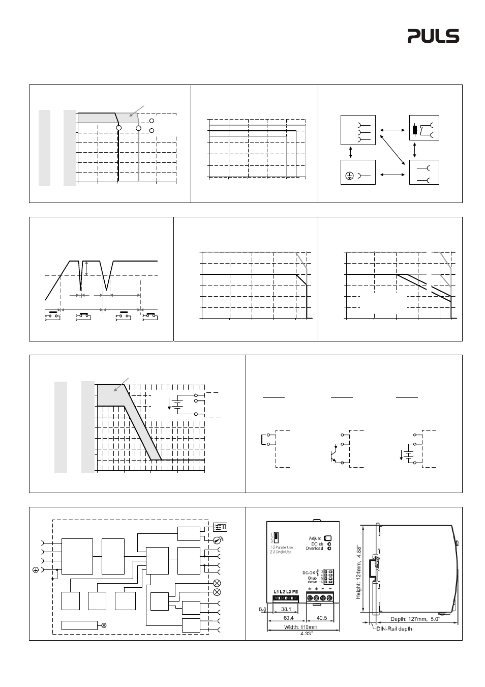
Fig. 9 / Bild 9 Functional Diagram / Funktionsschaltbild
Fig. 10 / Bild 10 Dimensions / Abmessungen
+
+
-
-
V
OUT
DC-ok
Contact
Output
Over-
Voltage
Protection
PFC
Converter
Input Fuses
Input Filter
Input Rectifier
Inrush Limiter
Transient Filter
Output
Voltage
Regulator
Power
Converter
Output
Filter
DC ok
Relay
Output
Voltage
Monitor
Output
Power
Manager
Temper-
ature
Shut-
down
Overload
LED
DC-ok
LED
L2
L3
L1
Single /
Parallel
Shut-
down
13
14
15
16
Event Datalogger
Shut-down
Input &
Remote
Control
PU-374.011.00-10B