PULS QS40.241 User Manual
Page 4
1-Phase Power Supply Instruction Manual
Bedienungsanleitung für 1-Phasen Stromversorgungen
Installation
Use DIN-rails according to EN 60715 with a height of 7.5 or 15mm. Mounting orientation must be
output and input terminals on the bottom. For other orientations see datasheet. Do not obstruct air
flow as the unit is convection cooled. Ventilation grid must be kept free of any obstructions. The
following installation clearances must be kept when power supplies are permanently fully loaded:
Left / right: 5mm (15mm in case the adjacent device is a heat source)
40mm on top, 20mm on the bottom of the unit.
Use in hazardous location areas
Units which are marked with "Class I Div 2" are suitable for use in Class I Division 2 Groups A, B,
C, D locations.
Units which are marked with
II 3G Ex nA nC IIC T3 Gc are suitable for use in Group II
Category 3 (Zone 2) environments and are evaluated according to EN 60079-0:2009 and EN
60079-15:2010.
WARNING EXPLOSION HAZARDS!
Substitution of components may impair suitability for this environment. Do not disconnect the unit
or operate the voltage adjustment unless power has been switched off or the area is known to be
non-hazardous. A suitable enclosure must be provided for the end product which has a minimum
protection of IP54 and fulfils the requirements of the EN 60079-15:2010.
Installation
Geeignet für DIN-Schienen entsprechend EN 60715 mit einer Höhe von 7,5 oder 15mm. Der
Einbau hat so zu erfolgen, dass sich die Eingangs- und Ausgangsklemmen unten befinden. Für
andere Einbaulagen siehe Datenblatt. Luftzirkulation nicht behindern! Das Gerät ist für
Konvektionskühlung ausgelegt. Es ist für ungehinderte Luftzirkulation zu sorgen. Folgende
Einbauabstände sind bei dauerhafter Volllast einzuhalten:
Links / rechts: 5mm (15mm bei benachbarten Wärmequellen)
Oben: 40mm, unten 20mm vom Gerät.
Betrieb in explosionsgefährdeter Umgebung
Geräte, die mit "Class I Div 2" gekennzeichnet sind, sind für den Einsatz in Klasse I Division 2
Gruppen A,B,C,D Umgebung geeignet.
Geräte, die mit
II 3G Ex nA nC IIC T3 Gc, gekennzeichnet sind, sind nach EN 60079-0:2009
und EN 60079-15:2010 getestet und kann in Gruppe II, Kategorie 3 (Zone 2) Umgebungen
verwendet werden.
ACHTUNG EXPLOSIONSGEFAHR!
Veränderungen am Gerät können die Tauglichkeit für diese Umgebung beeinträchtigen.
Anschlüsse nicht abklemmen und Spannungseinstellung nicht verändern, solange Spannung
anliegt oder die Umgebung als explosionsgefährlich gilt. Das Gerät muss mindestens in ein IP54
Gehäuse, welches den Anforderungen der EN 60079-15:2010 entspricht, eingebaut werden.
CE Marking
CE mark is in conformance with EMC directive 2004/108/EC, the low-voltage directive (LVD)
2006/95/EC and the RoHS directive 2011/65/EC.
EMC Immunity: EN 61000-6-1, EN 61000-6-2
EMC Emission EN 61000-6-3, EN 61000-6-4, FCC Part 15 Class B
CE Kennzeichnung
Das CE Zeichen ist angebracht und erklärt die Erfüllung der EMV Richtlinie 2004/108/EG, der
Niederspannungsrichtlinie 2006/95/EG und der RoHS Richtlinie 2011/65/EG.
Störfestigkeit: EN 61000-6-1, EN 61000-6-2
Störaussendung: EN 61000-6-3, EN 61000-6-4, FCC Part 15 Klasse B
Input Fuses
Internal input fuse included, not user accessible. The unit is tested and approved for branch
circuits up to 32A. An external protection is only required if the supplying branch has an ampacity
greater than this, however, in some countries local regulations might apply. Check local codes and
requirements. If an external fuse is necessary or utilized, minimum requirements need to be
considered to avoid nuisance tripping of the circuit breaker.
QS40.241, QS40.361, QS40.481: Use a minimum value of 16A B- or C-Characteristic breaker
QS40.244, QS40.484: Use a minimum value of 10A B- or 8A C-Characteristic breaker
Sicherungen am Eingang
Das Gerät besitzt eine eingebaute Eingangssicherung, die nicht anwenderzugänglich ist. Das
Gerät ist geprüft und zugelassen zum Anschluss an Stromkreisen bis max. 32A. Ein zusätzlicher
externer Schutz ist nur erforderlich, wenn der Speisestromkreis mit einem höheren Wert
abgesichert ist oder nationale Richtlinien es vorschreiben. Um ein fehlerhaftes Auslösen externer
Schutzelemente zu vermeiden folgende Minimalwerte nicht unterschreiten:
QS40.241, QS40.361, QS40.481: 16A B- oder C-Charakteristik
QS40.244, QS40.484: 10A B- oder 8A C-Charakteristik
Isolation and Dielectric Strength
(see Fig. 4)
The output voltage is floating and separated from the input according to SELV (IEC/EN 60950-1)
and PELV (EN 60204-1, EN 50178; IEC 62103, IEC 60364-4-41) requirements. Type and factory
tests are conducted by the manufacturer. Field tests may be conducted in the field using the
appropriate test equipment which applies the voltage with a slow ramp (2s up and 2s down).
Connect all phase-terminals together as well as all output poles before the test is conducted.
When testing, set the cut-off current settings to the value in the table below.
A B
C
D
Type Test (60s)
2500Vac
3000Vac
500Vac
500Vac
Factory Test (5s)
2500Vac
2500Vac
500Vac
500Vac
Field Test (5s)
2000Vac
2000Vac
500Vac
500Vac
Cut-off current setting
>20mA
>20mA
>40mA
>1mA
Galvanische Trennung und Isolationsfestigkeit
(siehe Bild 4)
Die Ausgangsspannung hat keinen Bezug zur Erde oder Schutzleiter und ist zum Eingang nach
den SELV (IEC/EN 60950-1) und PELV (EN 60204-1, EN 50178, IEC 62103, IEC 60364-4-41)
Standards getrennt. Typ- und Stückprüfungen werden beim Hersteller durchgeführt. Wieder-
holungsprüfungen dürfen mittels geeigneten Prüfgenerators mit langsam (2s) ansteigenden und
abfallenden Spannungsrampen in der Anwendung erfolgen. Vor den Tests sind alle Phasen wie
auch alle Ausgangspole miteinander zu verbinden. Während der Tests darf die Strom-
Abschaltschwelle nicht kleiner als der in der Liste angegebene Wert sein.
A B C D
Typprüfung (60s)
2500Vac
3000Vac
500Vac
500Vac
Stückprüfung (5s)
2500Vac
2500Vac
500Vac
500Vac
Wiederholungsprüfung (5s)
2000Vac
2000Vac
500Vac
500Vac
Strom- Abschaltschwelle
>20mA
>20mA
>40mA
>1mA
Hiccup
PLUS
Overload Characteristic
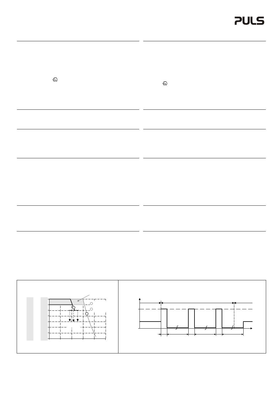
(see Fig. 1and 2)
The output current is electronically controlled. During an overcurrent situation, the output voltage
will be reduced after a defined time. If the voltage falls below 20V for the 24V units, 30V for the
36V unit and 40V for the 48V units, the unit switches to the Hiccup
PLUS
mode. In this mode, the
output switches off followed by a restart attempt after 17s for 2s. This cycle is repeated as long as
the overload or short circuit exists. If the overload or short circuit has been cleared, the device will
operate normally.
Hiccup
PLUS
Überlastverhalten
(siehe Bilder 1 und 2)
Der Ausgangsstrom ist elektronisch überwacht. Während einer Überstromsituation wird nach einer
bestimmten Zeit die Ausgangsspannung reduziert. Fällt die Spannung unter 20V bei 24V Geräten,
30V beim 36V Gerät oder 40V bei 48V Geräten schaltet das Gerät in den Hiccup
PLUS
Modus. In
diesen Modus schaltet das Gerät ab und macht nach 17s einen Startversuch mit einer Dauer von
2s. Der Vorgang wiederholt sich solange, bis die Überlast oder der Kurzschluss entfernt ist. Nach
entfernen der Überlast oder des Kurzschlusses schaltet das Gerät wieder in den Normalbetrieb.
Fig. 1/ Bild 1
Output Characteristic /Ausgangskennlinie, typ.
Fig. 2/ Bild 2
Hiccup
PLUS
Overload and Short-Circuit Behavior / Hiccup
PLUS
Überlast- und Kurzschlussverhalten, typ.
Output Current
0V
0
50%
100%
4V
8V
12V
28V
16V
20V
24V
150%
200%
250%
24V
Unit
0V
6V
12V
18V
42V
24V
30V
36V
36V
Unit
0V
8V
16V
24V
56V
32V
40V
48V
48V
Unit
Hiccup
PLUS
mode
Adjustment range
A
B
A
B
Short-term (4s)
available
Continuously
available
Output Voltage
Output
Current
0
I
SC
17s
17s
17s
2s
2s
2s
t
Short -circuit
Normal
operation
Normal
operation
I
SC
:
24V units: 65A
36V unit: 50A
48V units: 35A