PULS QS5.241-A1 User Manual
Page 4
QS5: Power Supply Instruction Manual
QS5: Bedienungsanleitung für Stromversorgung
CE Marking
CE mark is in conformance with EMC directive 2004/108/EC, the low-voltage directive (LVD)
2006/95/EC and the RoHS directive 2011/65/EU.
EMC Immunity: EN 61000-6-1, EN 61000-6-2
EMC Emission: EN 61000-6-3, EN 61000-6-4, FCC Part 15 Class B
CE Kennzeichnung
Das CE Zeichen ist angebracht und erklärt die Erfüllung der EMV Richtlinie 2004/108/EG, der
Niederspannungsrichtlinie 2006/95/EG und der RoHS Richtlinie 2011/65/EU.
Störfestigkeit: EN 61000-6-1, EN 61000-6-2
Störaussendung: EN 61000-6-3, EN 61000-6-4, FCC Part 15 Klasse B
Terminals and Wiring
(see Fig. 6)
Use appropriate copper cables that are designed for a minimum operating temperature of:
60°C for ambient temperatures up to 45°C,
75°C for ambient temperatures up to 60°C and
90°C for ambient temperatures up to 70°C.
Follow national installation codes and regulations! Ensure that all strands of a stranded wire enter
the terminal connection! Ferrules are allowed.
Input
Output, DC-OK Signal
Solid
wire
0.5-6mm
2
0.3-4mm
2
Stranded
wire
0.5-4mm
2
0.3-2.5mm
2
American wire gauge
20-10 AWG
28-12 AWG
Wire stripping length
7mm / 0.28inch
6mm / 0.25inch
Anschlussklemmen und Verdrahtung
(siehe Bild 6)
Verwenden Sie geeignete Kupferkabel, die mindestens für:
60°C bei einer Umgebungstemperatur bis zu 45°C,
75°C bei einer Umgebungstemperatur bis zu 60°C und
90°C bei einer Umgebungstemperatur bis zu 70°C zugelassen sind.
Beachten Sie nationale Bestimmungen und Installationsvorschriften! Stellen Sie sicher, dass
keine einzelnen Drähte von Litzen abstehen. Aderendhülsen sind erlaubt.
Eingang
Ausgang, DC-OK Signal
Starrdraht
0,5-6mm
2
0,3-4mm
2
Litze
0,5-4mm
2
0,3-2,5mm
2
AWG
20-10 AWG
28-12 AWG
Abisolierlänge
7mm / 0,28inch
6mm / 0,25inch
Indicators and Relay Contact
Overload LED
DC-OK LED
DC-OK Contact
Normal mode
OFF
ON
Closed
During BonusPower
®
OFF
ON
Closed
Overload (Vout < 90%)
ON
OFF
Open
Output short circuit
ON
OFF
Open
Temperature Shut-down
flashing
OFF
Open
No input power
OFF
OFF
Open
Anzeigelampen und Relaiskontakt
Overload LED
DC-OK LED
DC-OK Kontakt
Normalbetrieb AUS
EIN
geschlossen
Während BonusPower
®
AUS
EIN
geschlossen
Überlast (Vout < 90%)
EIN
AUS
offen
Ausgangskurzschluss EIN AUS
offen
Temperaturabschaltung blinken
AUS
offen
Keine Eingangsspannung
AUS
AUS
offen
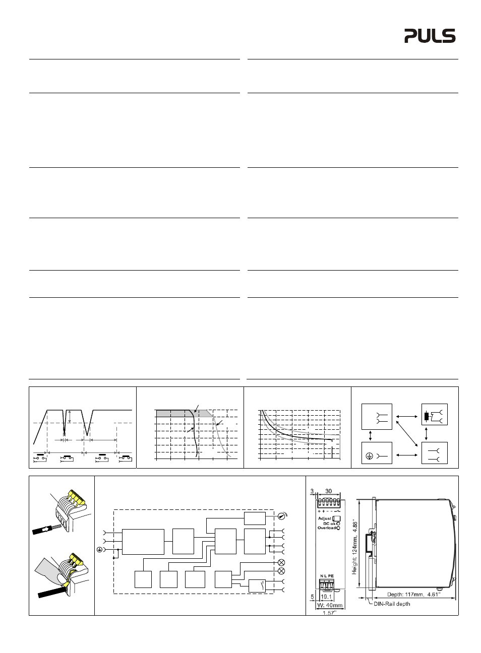
DC-OK Relay Contact
(see Fig. 1)
This feature monitors the output voltage, which is produced by the power supply, and is
independent of a return voltage from a unit which is connected in parallel.
Contact closes when the output voltage reaches the adjusted value after turn-on of the power
supply or when the output voltage reaches 90% after a dip in the output.
Contact opens when the output voltage dips more than 10%. Short dips will be extended to a
length of 250ms. Dips shorter than 1ms will be ignored.
Contact ratings: max.: 60Vdc 0.3A, 30Vdc 1A, 30Vac 0.5A, resistive load, min. current 1mA
DC-OK Relais Kontakt
(siehe Bild 1)
Diese Funktion überwacht die vom Gerät erzeugte Ausgangsspannung und lässt sich von einer
rückwärts eingespeisten Spannung nicht beeinflussen (z.B.: bei Parallelschaltung)
Kontakt schließt sobald nach dem Einschalten der Ausgang den eingestellten Wert erreicht oder
wenn nach Einbruch des Ausgangs die Spannung wieder >90% des eingestellten Wertes wird.
Kontakt öffnet sobald der Ausgang um mehr als 10% einbricht. Kurze Einbrüche werden auf
250ms verlängert. Einbrüche kürzer 1ms werden ignoriert.
Kontakt Belastbarkeit: max.: 60Vdc 0.3A, 30Vdc 1A, 30Vac 0.5A, (R-Last), min. Strom 1mA
Output- and Overload Characteristic
(see Fig. 2 and 3)
The units are no-load, overload and short-circuit proof. The units are designed to support loads
with a continuous power demand of up to 120W and a short-term (see Fig. 3) power demand of up
to 180W without damage or shut-down.
Ausgangs- und Überlastverhalten
(siehe Bilder 2 und 3)
Die Stromversorgungen sind leerlauf-, kurzschluss- und überlastfest und zur Versorgung von
Lasten mit einem Dauerleistungsbedarf bis zu 120W und einem kurzzeitigem (siehe Bild 3)
Leistungsbedarf bis 180W konstruiert ohne dabei Schaden zu nehmen oder abzuschalten.
Dielectric Strength
(see Fig. 4)
The output voltage is floating and separated from the input according to SELV (IEC/EN 60950-1)
and PELV (EN 60204-1, EN 50178; IEC 62103, IEC 60364-4-41) requirements. Type and factory
tests are conducted by the manufacturer. Field tests may be conducted in the field using the
appropriate test equipment which applies the voltage with a slow ramp (2s up and 2s down).
Connect all phase-terminals together as well as all output poles before the test is conducted.
When testing, set the cut-off current settings to the value in the table below.
A B
C
D
Type Test (60s)
2500Vac
3000Vac
500Vac
500Vac
Factory Test (5s)
2500Vac
2500Vac
500Vac
500Vac
Field Test (5s)
2000Vac
2000Vac
500Vac
500Vac
Cut-off current setting
>10mA
>10mA
>20mA
>1mA
Isolationsfestigkeit
(siehe Bild 4)
Die Ausgangsspannung hat keinen Bezug zur Erde oder Schutzleiter und ist zum Eingang nach
den SELV (IEC/EN 60950-1) und PELV (EN 60204-1, EN 50178, IEC 62103, IEC 60364-4-41)
Standards getrennt. Typ- und Stückprüfungen werden beim Hersteller durchgeführt. Wieder-
holungsprüfungen dürfen mittels geeigneten Prüfgenerators mit langsam (2s) ansteigenden und
abfallenden Spannungsrampen in der Anwendung erfolgen. Vor den Tests sind alle Phasen wie
auch alle Ausgangspole miteinander zu verbinden. Während der Tests darf die Strom-
Abschaltschwelle nicht kleiner als der in der Liste angegebene Wert sein.
A B C D
Typprüfung (60s)
2500Vac
3000Vac
500Vac
500Vac
Stückprüfung (5s)
2500Vac
2500Vac
500Vac
500Vac
Wiederholungsprüfung (5s)
2000Vac
2000Vac
500Vac
500Vac
Strom- Abschaltschwelle
>10mA
>10mA
>20mA
>1mA
Fig. 1 / Bild 1
DC-OK-Signal
Fig. 2 / Bild 2
Output Characteristic /Ausgangskennlinie
Fig. 3 / Bild 3
BonusPower
®
Time / Zeit
Fig. 4 / Bild 4
Insulation / Isolation
250ms
90% V
ADJ
<1ms
10%
open
V
OUT
= V
ADJ
open
closed
closed
>1ms
Output Voltage
0
0
2
6
8
10A
4
8
12
28V
16
20
24
4
Output
Current
short-
term
Adjustment
Range
continuous
Bonus Time
0
110
120
130
140
150
160%
1
2
3
7
4
5
6
8
9
10s
Output Power
min.
max.
typ.
A
D
C
B
B
Input
DC-ok
Earth
Output
-
+
N
L
Fig. 5 / Bild 5
Terminals / Anschlüsse
Fig. 6 / Bild 6
Functional Diagram / Funktionsschaltbild
Fig. 7 / Bild 7
Dimensions / Abmessungen
Insert wire /
Draht einführen
+
+
-
-
DC-ok
contact
Output
Over-
Voltage
Protection
PFC
Converter
Output
Voltage
Regulator
Power
Converter
Output
Filter
DC-ok
Relay
Output
Voltage
Monitor
Output
Power
Manager
Temper-
ature
Shut-
down
Overload
lamp
DC-ok
lamp
Input Fuse
Input Filter
Input Rectifier
Active Transient Filter &
Inrush Current Limiter
V
OUT
L
N
Snap the lever /
Hebel schließen
PU-348.011.00-10C