Renkus-Heinz STXLA/9 User Manual
Page 14
Line Array User’s Manual
Line Array User’s Manual
SYSTEM SETUP: ELECTRONICS
STLA Self-Powered Systems
STLA line array modules are self-powered with the PM-3 PowerNet Tri-Amplifier. The Class D amplifier section
and the Loudspeaker Specific Processing electronics require appropriate AC power. Audio inputs can be either
high-CMRR analog audio inputs with XLR looping connectors or CobraNet digital audio inputs. If a R-Control
remote control and supervision network is installed, its connections can be made via a separate twisted pair cable
and Phoenix connector or in systems having CobraNet, with the CobraNet connectors.
Source Signal
Source signal connections to aself-powered STLA array are quite straightforward. Connecting analog signal simply
requires one cable from the top module to the snake. Subsequent modules can then be connected using the PM-
3’s looping XLR inputs and outputs. Of course, if you intend to use level shading as part of your array design, you
will need to attenuate the inputs to all modules that receive different signal levels.
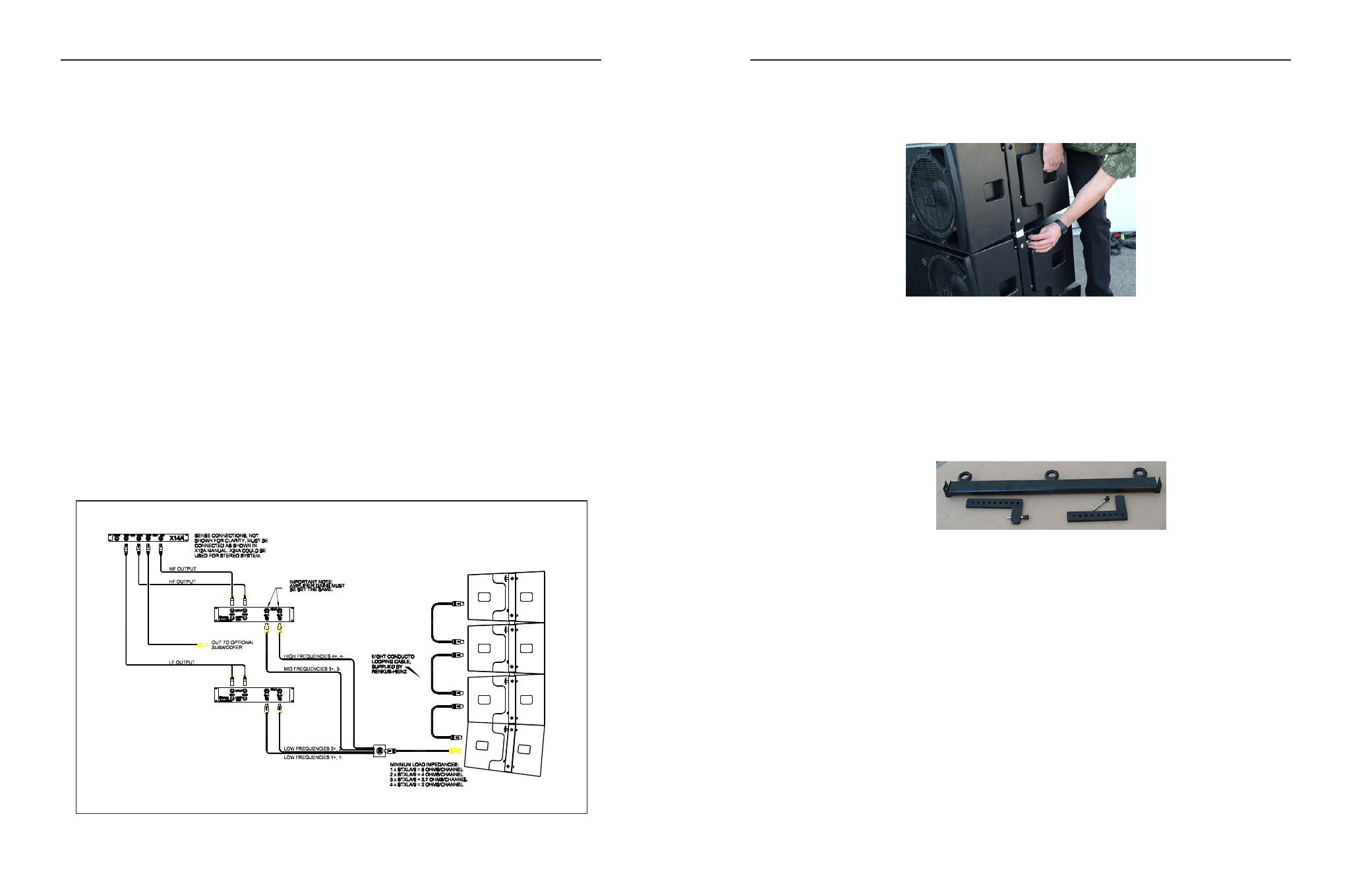
STXLA Externally-Powered Systems
STX Amplifier Selection
STXLA array modules are tri-amplified. For optimum performance we recommend the X14 Controller
and the following power amplifier ratings:
LF
1,000 to 2,000 watts, RMS @ 4 ohms
MF
400 to 800 watts, RMS @ 4 ohms
HF
160 to 320 watts, RMS @ 4 ohms
All amplifiers must have the same voltage gain.
To set medium or minimum splay angles, two operators (one per side of the enclosure) should lift the top
enclosure until the proper holes on the tie bar and receiving pin are aligned. Then insert the quick-release pin.
Check to make sure that both sides of the enclosure are set to the same splay angle.
The RHANGSTLA fly bar will support arrays up to 12 deep. It provides a simple way to alter the array’s tilt
angle without requiring multiple rigging points and motors.
14
19
NOT
r
“X” Series Processors may be replaced
by DS P Processors/ Crossovers.