Nexo Alpha System User Manual
Page 10
α
α
α
P 10
USER MANUAL
VERSION :1.01
DATE : 06/10/10
1
±
-
-
In VLF (S2)
In / Out VLF (S2)
2
±
-
-
In / Out LF (B1)
In / Out LF (B1)
3
±
-
-
In / Out MF
P : In / Out MF+HF
A : In / Out MF
SP8
#1
4
±
-
-
In / Out HF
P : Not connected
A : In / Out HF
1
±
-
-
In VLF (S2)
In VLF (S2)
2
±
-
-
In / Out LF (B1)
In / Out LF (B1)
3
±
-
-
In / Out MF
P : In / Out MF+HF
A : In / Out MF
SP8
#2
4
±
-
-
In / Out HF
P : Not connected
A : In / Out HF
P = MF-HF passive / A = MF-HF active
2.1.2. C
ABLES
Nexo recommends the exclusive use of multi-conductor cables to connect the system : the cable
kit is compatible with all the cabinets, and there is no possible confusion between VLF, LF, MF
and HF sections.
Cable choice consists mainly of selecting the correct cable section (size) in relation to the load
resistance and the cable length. Too small a cable section will increase its serial resistance, this
would induce power-loss and response variations (damping factor).
For a serial resistance less or equal to 4% of the load impedance (damping factor = 25), the maximum
cable length is given by :
L
max
= Z x S S in mm
2
, Z in Ohm, L
max
in meters
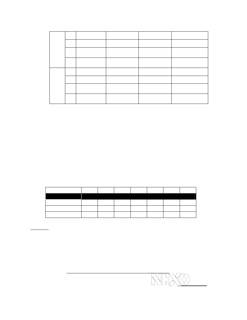
The table below indicates these values, for 3 common sizes.
Load Impedance (
Ω)
2 3 4 6 8 12
16
Cable section
Maximum Length (meters)
1,5 mm² (AWG #14)
3
4.5
6
9
12
18
24
2,5 mm² (AWG #12)
5
7.5
10
15
20
30
40
4
mm²
(AWG
#10) 8 12 16 24 32 48 64
Important :
• long speaker cables induce capacitive effect that damage the quality of the audio signal (up to hundreds
of pF depending on the quality of the cable, with a low-pass effect in high frequencies) ;
• if long speaker cables are to be used, insure that they do not remain coiled while in use. .