Compressed air supply air pressure – American Dryer Corp. ADH-120 User Manual
Page 30
26
4. Steam Damper Air System Connections
The ADH-120 is manufactured with a pneumatic (piston) damper system or door interlock which requires
an external supply of clean compressed air. The air connection is made to the steam damper solenoid valve
which is located at the rear inner top area of the dryer just above the electric service relay box.
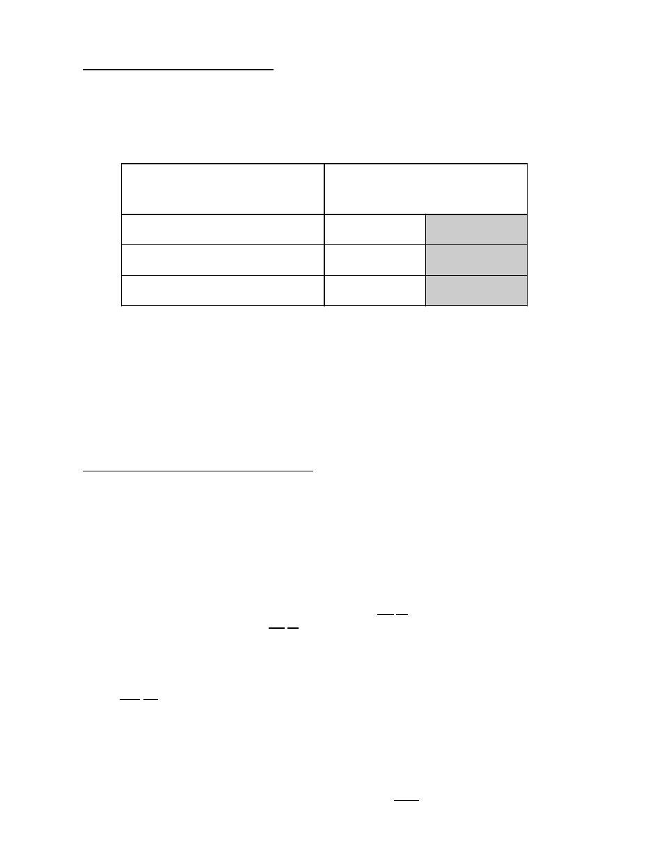
a. Air Requirements
b. Air Connection
Air connection to system --- 1/8-inch N.P.T.
c. No air regulation or filtration is provided with the dryer. External regulation/filtration of 80 PSI (5.51
bars) must be provided. It is suggested that a regulator/filter gauge arrangement be added to the
compressed air line just before the dryer connection. This is necessary to insure that correct and clean
air pressure is achieved.
5. Steam Damper Air Piston Operation Adjustment
When installing or adjusting the steam damper the following steps must be taken for proper operation of the
system.
a. The linkage support assembly is placed on the center bar inside the plenum between the coils. The
assembly must be positioned such that the locking collar is facing the rear of the dryer. When installing,
examine the linkage assembly to be certain that collar has been welded on the proper side of the assembly.
Refer to figure 1. The collar should not be locked into place on the center bar yet.
b. Facing the front of the coil assembly, the small linkage arm will be fastened to the left side of the linkage
assembly and the large linkage arm will be positioned to the right. Each linkage is fastened with a clevis
pin, a cotter pin, and a sufficient number of washers to allow the linkage to swivel without sloppiness.
c. The opposite side of each linkage will then be fastened to the appropriate damper assembly. There are
five (5) holes on each damper flange. The best adjustment is usually found in the center hole. However,
this may not hold true on every damper assembly due to manufacturing tolerances. The linkage is then
fastened to the damper flange in the same manner as step two (2). Refer to figure 1. The linkage
support assembly should be turned counterclockwise (CCW) until the damper assemblies seat securely
against the steam coils and the setscrew is to be tightened securely.
d. The lever arm assembly should then be positioned on the center bar on the front of the steam damper
assembly. With the damper assemblies seating securely against the steam coils, the lever arm should
be positioned between 8:00 and 9:00. These connections are ALL shown in figure 2.
COMPRESSED
AIR SUPPLY
AIR PRESSURE
Normal
80 PSI
5.51 bars
Minimum Supply
70 PSI
4.82 bars
Maximum Supply
90 PSI
6.21 bars
Shaded areas are stated in metric equivalents