Remove coolant from hot systems – UView Vacufill Coolant Exchanger User Manual
Page 5
TO STOP FILLING COOLANT
When the vacuum gauge reading stops, set to "
TEST
"
position.
For side tank vehicles, fill coolant to proper level before setting valves.
NOTE:
If gauge reading continues to drop and the container is almost empty, add more coolant to the container
until the gauge reading stops.
2. Remove RadNeck assembly from cooling system.
3. Top-up cooling system to proper level.
4. Start vehicle to warm up cooling system. Add coolant if necessary before replacing cap for the cooling system.
TO FILL NEW COOLANT INTO COOLING SYSTEM
Vehicle cooling system must be evacuated. See "TO EVACUATE AIR" instructions.
1. Fill clear container with the recommended coolant for the vehicle.
NOTE: Make sure there is more coolant in the container than the system requires.
coolant into the clear container.
Set to "
REMOVE" and to "OFF" .
Set to "
FILL". The gauge will start to drop as coolant flows into the cooling system.
Radiator is full when the gauge stops. For vehicles with side tanks, stop when proper fluid level
is reached.
REMOVE COOLANT FROM HOT SYSTEMS
Cooling systems run at high temperature and pressures. Pressure must be
relieved before removing cooling system cap.
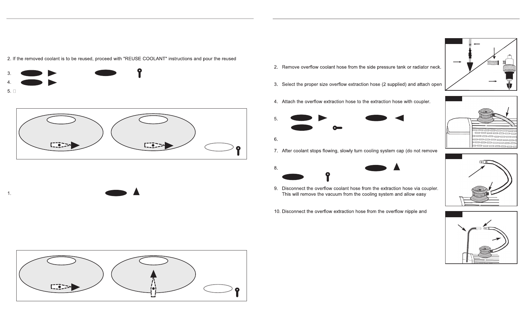
Determine if the overflow nipple fits a 5/16" or 3/8" size hose.
(Figure 5)
end to the overflow nipple with clamp.
(Figure 6)
(Figure 7)
Set to "
REMOVE" and to "REMOVE"
and to "
ON" (airline is already attached to VACUFILL).
Vacuum gauge will start to rise and coolant will flow into hose.
cap at this time). This will allow more coolant to flow into the VACUFILL.
Once coolant has stopped flowing, turn to "
TEST" then
to "
OFF" position.
removal of the cooling system cap.
(Figure 7)
reconnect overflow coolant hose.
11. Now follow the instructions for "Removing Coolant from an Open System".
WARNING! Gloves and protective eyewear must be worn. Risk of burns may
result from high coolant temperatures and pressures.
6
3
Figure 6
Figure 7
B
D
EXTRACTION
HOSE
Figure 5
OVERFLOW
HOSE
OVERFLOW
NIPPLE
COUPLER
CONNECTION
D
E
VALVE 1
VALVE 2
VALVE 2
B
REMOVE
B
VALVE 1
VALVE 2
"OFF"
VALVE 3
FILL
E
"
OFF"
REMOVE
B
TEST
D
VALVE 3
VALVE 1
VALVE 3
VALVE 3
VALVE 2
VALVE 2
VALVE 1
VALVE 2
VALVE 3
C
OVERFLOW
EXTRACTION HOSE
OVERFLOW
EXTRACTION HOSE
1. Disconnect the Extension Tube Assembly or RadNeck Assembly from the
extraction hose via the coupler connection. (
Figure 4)
EXTENSION
TUBE
ASSEMBLY
Figure 4
RADNECK
ASSEMBLY
EXTRACTION HOSE